Continue to Site

Welcome to EDAboard.com

Welcome to our site! EDAboard.com is an international Electronics Discussion Forum focused on EDA software, circuits, schematics, books, theory, papers, asic, pld, 8051, DSP, Network, RF, Analog Design, PCB, Service Manuals... and a whole lot more! To participate you need to register. Registration is free. Click here to register now.

[SOLVED] to design the circuit to improve circuit to noise ratio

Status
Not open for further replies.

fareen

Full Member level 3
Joined
Oct 31, 2010
Messages
154
Helped
4
Reputation
8
Reaction score
4
Trophy points
1,298
Activity points
2,193
hello pppl,
i have an other task on which im blank
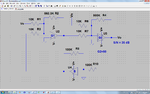
i have to design a circuit to to improve signal to noise ratio by using following stages
pre amplifer without noise
amplifer with noize signal
feedback
the gain of the amplifer should be 50db
and required snr=35db
can suimbody help??
thanks in advance**broken link removed**
i need to replace the block with circuit components 32cc7a87774.gif32cc7a87774.gif
 
Last edited:

Thank you for contacting me but this kind of problems are rather academic to me since their solution depends on materials given in a course. So I have to read the course book (or books) to remember how the design should be directed. The answer might be easy after remembering the few basic theorems that the design should be based on.

For instance, my first remark on your block diagram is that I don’t see any sign on it.
Is it supposed to also find out the appropriate signs at the entries of the adders and the signs of the gains G1 and G2 as well?
 

we just need to see that signal to noise ratio improve by this step up
g1 and g2 are two amplifier one with noise g2 and g1 without noise that will only amplify the signal
while beta is negative feedback
 

So the problem is to calculate the factors of the block diagram first. Otherwise, the solution circuit will be presented as a topology that shows the components and their connections but without any values. What do you think?
 

yes we have to calculate the factors first
but given is g2=50db
and snr=35db
 

Are you kidding? Even after 35 years, I am happy that I have no more homework :grin:

I don't think it is difficult for you. You know how to write simple equations.
If I am not wrong, you need to write two equations (using names); one for each path.
Then you will try to remember what S/N means as terms on a circuit.
These terms will be surely in your two equations.
So the next step is re-arranging the two in one equation which includes the terms of S/N.
And ooops... you will find the condition that satisfies your last equation after replacing the given data.

Added:
I am really surprised why no one tries to give a hand :wink:

Added:
I am not myself 100% sure how to do it. I know it is simple but I have to be careful at every step and I don't know if I have time to read about the subject before I reply you.
What is an amplifer? Vout= Gain*Vin and what is an adder? Vout = V1 + V2 Just have a look on your diagram and write these simple formulas one after another.
By the way did you read the definition of S/N... you have to help me too :wink:

For example I am not sure if:
S/N = (Signal Power) / (Noise Power)
S/N (db) = 20 log [(Signal Power) / (Noise Power)]
or
S/N = [(Signal Vrms) / (Noise Vrms)]^2
S/N (db) = 20 log [(Signal Power) / (Noise Power)]
 
Last edited:

how???
what two equations???
help me with the calculation
plz plz aur im so dead:cry:

---------- Post added at 21:05 ---------- Previous post was at 19:48 ----------

[I am really surprised why no one tries to give a hand /QUOTE]
this isnt doing ant good
 
Last edited:

this from where i read the topic
 

Attachments

  • untitled.JPG
    untitled.JPG
    1.1 MB · Views: 119

Thank you.

First, in your case S/N = Signal V / Noise V = Vs/Vn

To solve for S/N, we need first to find Vout = K1*Vs + K2*Vn which means Vout has two components one related to the good signal and the other to the noise signal.

I noticed that the book example is like your problem where A2 -> G1 and A1 -> G2

Therefore
S/N = Vs/Vn * G1
Do you need the derivation steps?
OK
At the input adder:
V1 = Vs + B*Vo
At the second adder:
V2 = V1*G1 + Vn = ( Vs + B*Vo)*G1 + Vn
Therefore:
Vo = V2 * G2 = [ ( Vs + B*Vo)*G1 + Vn] * G2 = ( Vs + B*Vo)*G1*G2 + Vn * G2
We will try to bring the term having Vo in the right side to the left side:
Vo = Vs*G1*G2 + B*Vo*G1*G2 + Vn*G2
Vo - B*Vo*G1*G2 = Vs*G1*G2 + Vn*G2
Vo*(1 - B*G1*G2) = Vs*G1*G2 + Vn*G2
Vo = Vs * (G1*G2)/(1 - B*G1*G2) + Vn * G2/(1 - B*G1*G2)
Finally
S/N = (Vo generated by Vs) / (Vo generated by Vn)
S/N = [Vs*(G1*G2)/(1 - B*G1*G2)] / [Vn*G2/(1 - B*G1*G2)]
S/N = Vs/Vn * G1


What is confusing me is:
S/N (in db) = 20*log (S/N)
and we have two unknows in our S/N
Vs/Vn and G1
Should we suppose Vs/Vn = 1 ?!
 
Last edited:

yes i would appreciate that

---------- Post added at 22:12 ---------- Previous post was at 21:57 ----------

Vs/Vn are the ratio of output signal or input signal????
if input signal than we can considere it 1 if output then i think 50
 

Vs/Vn are the ratio of output signal or input signal????
At the inputs, which means how stronger Vsignal is in comparison to Vnoise (at the inputs)
S/N gives an indication how their ratio (originally at the inputs) becomes at the output node.

So you are sure that:
S/N in db = 20 log(S/N)
I will correct it in my previous post.

Do you know how we can get the amplifier gain from Vo above?

Is it...
Vo/Vs = (G1*G2)/(1 - B*G1*G2)
By the way, B is negative since it is supposed to a negative feedback.

Usually we write the amplifier gain in this case as (taking the sign of B into account):
Vo/Vs = 1/(1/(G1*G2) + B)
and 1/G1*G2 << B
Vo/Vs = 1/B
If this is the case:
50 db = 20 log (1/B)
B = 1/316

so
G1*G2 >> 316
G2 >> 316/56 >> 5.6
G2 >> 5.6
 
Last edited:

as from the dervation its clear that Vs/Vn is input signal so we will considere it 1
and from that we can find g1=56.23v/v
finding this next we wil have to calculate beta
but the output is unknown?
or should we consider beta one??

---------- Post added at 22:57 ---------- Previous post was at 22:22 ----------

Vo is the sum of two inputs Vs * (G1*G2)/(1 - B*G1*G2) + Vn * G2/(1 - B*G1*G2)
do you think we can do that Vo/Vs = (G1*G2)/(1 - B*G1*G2)???
 
Last edited:

Usually we refer to the amplifier gain as Vo/Vs only.
Vn is just a parasite signal (it may enter in any point).

Vo/Vs is not 50db G2 gain is 50v/v,not the overall gain
You know better than I.
So G2 = 316 right?

I just noticed 50v/v .... from where does it come?!

Ok... I revised your previous posts... it seems by mistake things are messed.

So now
S/N = 35db
G2= 50

We found that
G1 = 56.23

If B=-1
We can draw a circuit using opamps (one for each block)... ok?
 

Attachments

  • Feedback_Noise.png
    Feedback_Noise.png
    105.7 KB · Views: 102
Last edited:

Vo/Vs is not 50db G2 gain is 50v/v,not the overall gain

---------- Post added at 23:16 ---------- Previous post was at 23:07 ----------

G2 is 50v/v
the gain of noisy amplifer is 50v/v
not the gain of whole amplifer

---------- Post added at 23:19 ---------- Previous post was at 23:16 ----------

given by the instructor

---------- Post added at 23:38 ---------- Previous post was at 23:19 ----------

So now
S/N = 35db
G2= 50

We found that
G1 = 56.23
very correct now we need to find out beta

---------- Post added 18-06-11 at 00:03 ---------- Previous post was 17-06-11 at 23:38 ----------

i thought of the same but how do decide for beta circuit cant it be a resistive circuit or opamp with unity gain is fine???
and shouldnt we use a summer when adding amplified signal and noise
 

G1 has the same gain for Vs and the feedback signal. The same for G2, it has the same gain for G1V1 and Vn. So at both inputs there is an adder.
Since we don't pay for the opamp... one in excess won't cost us anything but it eases the work :wink:

Note: I usually don't impose on myself more conditions not required :grin: And if one is important it should be stated clearly otherwise no one can blame us :twisted:
 
Last edited:

can you send me the files??
 

Which one? You mean you have LTspice.

Added:
It was just an illustrative circuit. It needs to be completed if you look to simulate it. I think you will ask me to complete it :)
 
Last edited:

yes,lt spice files

quite true
actually i made a circuit sumthing like this but i had a power breakdown and file gets deleted
and i have hell lot work for monday
2 lab viav
lab test
lab reports
quiz
assignment
plus this design
and i have done nothing
so i am in really bad situation right now:(
 
Last edited:

yes,lt spice files
actually i made a circuit sumthing like this but i had a power breakdown and file gets deleted
so i am in really bad situation right now:(

After I wrote you a reply, edaboard deleted it before I had the chance to copy it while writing.
So here I am again.

It seems you expect me keep working on your homework... but we didn’t agree first on the salary. :smile:

I believe you are an intelligent student but you like to skip some steps with the hope to speed up your work.
But I hope you don't really believe that some of your classmates have a more powerful brain than yours... or have more time than you do?
In any case, it is not wrong to ask for help, in fact one needs a real courage to do it and say “Help me”.
On the other hand, helping is usually much easier (and as you know, it could give the helper the feeling of superiority :twisted: ).

I will try to complete the circuit for you. But please remember, it isn’t meant a solution for a real project.
In courses, problems are given to clarify one (or more) points like theorems or method of analysis... etc.
So the idea of our solution is more important than the circuit itself. It is about a method of increasing S/N at the amplifier output.

Personally I try to figure out how we let the comparison of the S/N be meaningful in our problem. If we let B=1 then the amplifier gain will be close to 1. But without the idea of feedback (that is adding the noiseless G1 and B) the amplifier gain is G2=50. I mean we were comparing two amplifiers having different gains. If I am not wrong we need to let the gain of the new amplifier (with feedback) equal to the original gain G2, though this won’t change the S/N since it depens on G1 only (I wonder what is in the mind of your lecturer).

Without feedback
Vo/Vs = G2
With feedback
Vo/Vs = (G1*G2)/(1 + B*G1*G2)
Therefore
(G1*G2)/(1 + B*G1*G2) = G2
G1/(1 + B*G1*G2) = 1
1 + B*G1*G2 =G1
B = (G1 – 1)/(G1*G2)
B= (56.23-1)/(56.23*50)
B=1/50.9 (it is almost as 1/G2)

What do you think?
 

Status
Not open for further replies.

Part and Inventory Search

Welcome to EDABoard.com

Sponsor

Back
Top