Continue to Site

Welcome to EDAboard.com

Welcome to our site! EDAboard.com is an international Electronics Discussion Forum focused on EDA software, circuits, schematics, books, theory, papers, asic, pld, 8051, DSP, Network, RF, Analog Design, PCB, Service Manuals... and a whole lot more! To participate you need to register. Registration is free. Click here to register now.

[SOLVED] TL494 PWM ISSUE in LTSPICE

Status
Not open for further replies.

sabu31

Advanced Member level 1
Joined
Jan 28, 2011
Messages
432
Helped
12
Reputation
24
Reaction score
13
Trophy points
1,298
Activity points
5,038
Dear All,

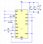
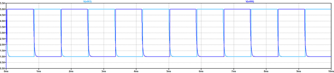
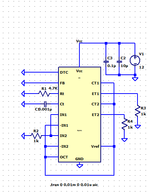
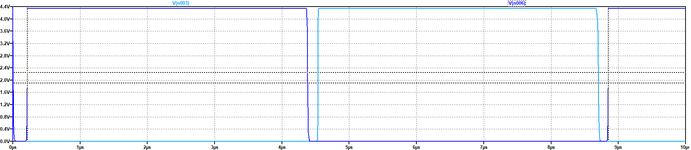
I am trying to get TL494 to generate 120Khz PWM in complementary mode with 50% duty Ratio. However, I am getting overlap in the waveform and also cannot reduce PWM to below 10kHz without complete overlap. Moreover, there is an offset of 1V in PWM output. I am attaching the circuit diagram and waveforms for your reference. Please let me know what changes are required or any references.
 

Attachments

  • BASIC_CIRCUIT.png
    BASIC_CIRCUIT.png
    23.6 KB · Views: 132
  • Waveform.png
    Waveform.png
    24.6 KB · Views: 102

Hi,

the attached signal shows a frequency of about 660 Hz (T = ~1.5 ms). According to your selected R_T and C_T value, the ocillator should operate at 1.1 kHz. If you have a look on Fig. 2 in [1], you will see, the oscillator frequency it two times the output frequency. Especially, as you have tied the OCT pin to VCC (according to the datasheet it should be tied to Vref).

So you clearly operate the PWM below 10 kHz without complete overlap. Please try to connect OCT to Vref. Also, do not leave the outputs floating, connect a load e.g. the shown one to test the rise and fall time. With the load you can check the output behaviour.

[1] https://www.onsemi.com/pdf/datasheet/tl494-d.pdf

BR
 

    sabu31

    Points: 2
    Helpful Answer Positive Rating
Hi,

Show your complete circuit.
Where is the scope connected to?

Why don't you use schematic given in the datasheet?
I mean: if you want to compare the results you need to use the same test conditions.

Why do you say you want 120kHz, then complain that it does not go below 10kHz ... while the picture shows about 0.6kHz.
Three completely different values?
0.6kHz is below 10kHz..
If you want 120kHz, then why don't you set Rt and Ct to get 120kHz?

--> Follow the datasheet snd you will get the expected results.

Klaus
 
  • Like
Reactions: sabu31

    sabu31

    Points: 2
    Helpful Answer Positive Rating
Thanks all for the reply. I got the results by terminating the E1 and E2 with 1k resistors. And connecting OCT to Vref apart from changing the values of Rt Ct. Using Standard resistor I am getting 115kHz
 

Attachments

  • BASIC_CIRCUIT.png
    BASIC_CIRCUIT.png
    11.5 KB · Views: 97
  • Waveform.png
    Waveform.png
    16.1 KB · Views: 94

Hi,

"Reference" usually is a precise - and thus sensitive - analog signal. It is not a power supply.

I don´t recommend to use any analog reference on digital signals (unless it is designed for this purpose),
especially not without a capacitor to stabilize the voltage on the sharp digital edges.

It´s not clear whether the Reference output is stable with an external capacitor.

I´d rather use an external 5V supply (Zener, voltage regulator... and capacitor)

***
Of course you can´t expect same timing with 1k to GND instead of 150R to VCC.

Klaus
 

Status
Not open for further replies.

Similar threads

Part and Inventory Search

Welcome to EDABoard.com

Sponsor

Back
Top