lynx_phoenix
Newbie level 5
Ok, first of all hi all, i'm new here, nice to meet ya all, i guess
this is my circuit
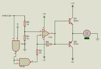
i made it so i can control dc motors, just left/right and enable functionality. in simulations it works great. i know simulations aren't always correct and it does look a bit too bare even to me, but as far as i understand it, it should at least follow its general designed behavior, which is switching either transistor on/off or switching them both off. basically i wire the opamp as a switch: when enable is on, l/r is either larger or smaller than enable, making it produce approx. +-12V at the opamps output depending on which case it is - when enable is low, both inputs go low because of the NAND gates.
i tried this once and it worked, with those resistors. its for my final assignment for my degree. i felt assured it would work, because everything i knew about these components and the circuit told me so. then we made this same circuit again for the final build, connect it to the motors and nothing worked properly. some motors were turned on permanently, or would behave erratically - tried it both with a microcontroller switching the enable and l/r inputs and without one. so i made it again on a breadboard and found out that the tl082, even new ones i hadn't ever used, were outputing random voltages - i measured one whos inputs were not even wired and i got -9,5V at its output. others would have a stable 2,5V output - and some would just output a random but steady voltage when they should be producing 0V, but behaved properly when their inputs had a difference, giving approx. +-12V. only sometimes, some of them worked properly - with properly i mean as designed.
did i mess it up? is this circuit supposed to work or is it wrong? i cant tell cause i actually had to learn a lot of things on my own and besides the classic thing about opamps needing feedback in order to work linearly, i never read anything to prepare me for the random behaviour of the tl082s.
thanks in advance for any clues and sorry for the slightly agitated post - this cost me my deadline and now i have to wait till september...