Continue to Site

Welcome to EDAboard.com

Welcome to our site! EDAboard.com is an international Electronics Discussion Forum focused on EDA software, circuits, schematics, books, theory, papers, asic, pld, 8051, DSP, Network, RF, Analog Design, PCB, Service Manuals... and a whole lot more! To participate you need to register. Registration is free. Click here to register now.

Tips from you for electronic board design

Status
Not open for further replies.

endrit

Newbie
Joined
Dec 2, 2020
Messages
5
Helped
0
Reputation
0
Reaction score
0
Trophy points
1
Activity points
38
Hello everyone, first of all I wish you a good day,
I am a student from the faculty of electrical engineering, and I undertook to design an electronic board.
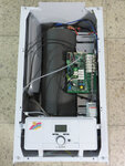
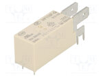
I am making a superficial description of the project, the project will be implemented in an electric boiler, and the purpose of the project is for the heaters to be controlled by the microcontroller via relays.
So what I ask of you is any advice ,if you have encountered any problems during the design, and how we could make this board have a good longevity?

sincerely
 

Hi,

We can not know your requirements. We don't know current, voltage, phase count, AC or DC, temperatures, precision, switching times...

I guess you need to provide some technical informations.

Klaus
 

the project will be implemented in an electric boiler

This suggests a high humidity environment, and/or water spraying during repairs and maintenance, etc. Therefore the board should have appropriate precautions such as a coating of water-resistant lacquer.

Also high temperature precautions, especially if the board is attached directly to the heating equipment.

Relays may need replacing every so often. Does your board make it easy to do so? Or, is it better to mount the relays off the board?
 
Hi,

We can not know your requirements. We don't know current, voltage, phase count, AC or DC, temperatures, precision, switching times...

I guess you need to provide some technical informations.

Klaus

thank you for your replica, the electric boiler will be used for home heating and will be 3 phase which will have 24 kW. While the board will contain 8 relays, so through the relays the heaters will be controlled The water temperature will be max 75 ° C and the water temperature in the water tank will be measured with an NTC thermistor. In the code for the microcontroller I will program that for every 0.5 ° C to stop it from a relay so if SetPoint is 50 ° C and T.water will be 49.5 ° C then in this case it will be just a relay of ndizur and in, but if Tset 50 ° C and Twater is <46 ° C then in this case all heaters will be activated
 

This suggests a high humidity environment, and/or water spraying during repairs and maintenance, etc. Therefore the board should have appropriate precautions such as a coating of water-resistant lacquer.

Also high temperature precautions, especially if the board is attached directly to the heating equipment.

Relays may need replacing every so often. Does your board make it easy to do so? Or, is it better to mount the relays off the board?

Hello, thanks for your reply, "electric boiler architecture" will be like this picture that is attached below


Community Verified icon
 

Attachments

  • 53151_Product.jpg
    53151_Product.jpg
    321.6 KB · Views: 160

Hi,

so we now have a better idea what you need.
I don´t expect much humidity at normal conditions. Ambient temperature may be higher than room temperature.
I see no need for the relay to be mounted off PCB. But you need to keep high power / high voltage in good distance to the microcontroller.

Avoid sparks at the relay contacts (MOV, snubber). This will increase contact lifetime as swell as reduce EMI to the microcontroller.
Also properly selected relays should have a >10 years lifetime. No need for frequent replacement. Take semiconductor relays with zero cross switching into consideration.

Microcontroller needs a properly designed PCB. Urgent: a solid GND plane. Use EMI/EMC filters at all board_I/Os. Use a fast ceramics capacitor at each power supply pin of each IC. Use the watchdog feature of the microcontroller, so it restarts itself in case of any software problem (even EMC related).

I recommend you to draw an overview sketch of the electronics hardware.

Klaus
 
  • Like
Reactions: endrit

    endrit

    Points: 2
    Helpful Answer Positive Rating
Hi,

so we now have a better idea what you need.
I don´t expect much humidity at normal conditions. Ambient temperature may be higher than room temperature.
I see no need for the relay to be mounted off PCB. But you need to keep high power / high voltage in good distance to the microcontroller.

Avoid sparks at the relay contacts (MOV, snubber). This will increase contact lifetime as swell as reduce EMI to the microcontroller.
Also properly selected relays should have a >10 years lifetime. No need for frequent replacement. Take semiconductor relays with zero cross switching into consideration.

Microcontroller needs a properly designed PCB. Urgent: a solid GND plane. Use EMI/EMC filters at all board_I/Os. Use a fast ceramics capacitor at each power supply pin of each IC. Use the watchdog feature of the microcontroller, so it restarts itself in case of any software problem (even EMC related).

I recommend you to draw an overview sketch of the electronics hardware.

Klaus
Hi,
i am thinking of using an electromagnetic relay but the relay should be "power relay" as attached below. The relay should be controlled by an optocoupler, ie the optocoupler should be controlled by the microcontroller and the optocoupler should release 12Vdc voltage to the relay.

ps . Thanks for the help, if I am doing something wrong in circuit, I apologize as I am still in studies
 

Attachments

  • 487495_1.jpg
    487495_1.jpg
    30.5 KB · Views: 168

Hi,
The relay should be controlled by an optocoupler, ie the optocoupler should be controlled by the microcontroller and the optocoupler should release 12Vdc voltage to the relay.
I sometimes see this. But it is nonsense to control a realy (which is an isolating device) with an optocoupler (which is another isolating device).
--> Use a simple bjt and a free wheeling diode. Or a ULN2xxx. Cheaper than an optocoupler, no performance degradation (like an optocoupler) and no drawback.

Klaus
 

    endrit

    Points: 2
    Helpful Answer Positive Rating
Hi,
I sometimes see this. But it is nonsense to control a realy (which is an isolating device) with an optocoupler (which is another isolating device).
--> Use a simple bjt and a free wheeling diode. Or a ULN2xxx. Cheaper than an optocoupler, no performance degradation (like an optocoupler) and no drawback.

Klaus

Thank you sincerely for your help. ULN2xx seems to me a good solution. All the best
 

Status
Not open for further replies.

Similar threads

Part and Inventory Search

Welcome to EDABoard.com

Sponsor

Back
Top