Continue to Site

Welcome to EDAboard.com

Welcome to our site! EDAboard.com is an international Electronics Discussion Forum focused on EDA software, circuits, schematics, books, theory, papers, asic, pld, 8051, DSP, Network, RF, Analog Design, PCB, Service Manuals... and a whole lot more! To participate you need to register. Registration is free. Click here to register now.

TIP35C malfunctioning

Status
Not open for further replies.

assadmahmood

Junior Member level 3
Joined
Oct 23, 2011
Messages
30
Helped
0
Reputation
0
Reaction score
0
Trophy points
1,286
Location
Karachi Pakistan
Visit site
Activity points
1,531
Greetings EveryBody!
I am using TIP35C darlington pair transistor IC. The prblem is that I am giving 24VDC, 3Amp on collector and supplying 5VDC, 1Amp on base, there is a solenoid between emitter and ground. Then I got the same voltage on solenoid as base voltage which means that I.C is not conducting from collector to emitter.
I also tried by 12V as base voltage but the result remain the same,

Any suggestion>?
 

Please post a schematic. It doesn't sound like anything is wrong, an emitter follower configuration has a voltage gain of less than 1 so the emitter voltage should be slightly less than the base voltage which is as you describe.

Brian.
 

TIP35C is not a darlington or IC.:arrow:

2515321000_1368032704.jpg


Connect emitter to ground. Connect a resistor in series with 5V supply to reduce current to base. Solenoid is connected to collector and +ve supply. A diode is also required for protection against back emf.
 

Do as betwixt told....
Please post a schematic.
So we can look the problem.
 

ssss.jpg

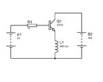
This is the schematic,
I guess Mr.elecbaba is right, I should connect solenoid between battery and collector.
Yes free wheel diode is there in hardware.
 

It's worth remembering that inside the transistor there is a P-N junction between the base and emitter and consequently has a fairly constant voltage drop once it has started to conduct. What you did was power the solenoid from the base current through the P-N juntion so you actually had approximately Vb - 0.7V across it. Moving it to the collector lets the transistor work as a switch, the base current controlling the current between collector and emitter pins and hence operating the solenoid.

You could have left the solenoid in the emitter if you injected base current through the base - emitter junction but the source could not then be ground at one end.

Brian.
 
If TIP35C has to be drive by a MicroController or any digital IC then is it necessary to use any small signal transistor between them for better performance to drive TIP35C by an IC???
 

Probably but not necessarily.

The TIP35 is a relatively low gain device so for a given collector current it will need a relatively high base current. The calculation is Ib = Ic/hfe but in a digital switching circuit you should allow for significantly more current being needed to ensure the transistor switches fully on when driven. This probably means it will need more base current than a microcontroller can supply. Your options are to use another transistor between the micro and TIP35 as a current booster, to change the TIP35 to a darlington type which has higher gain and therefore needs less base current or, you could use a MOSFET device instead of the TIP35. A MOSFET used as a switch draws almost no input current so in most cases can be driven either diectly or through a resistor from a micro output pin.

Brian.
 

Mr.Betwixt your reply was awesome and cleared my concepts many thanks for that,
Can you suggest me any MOSFET name and number which can drive 5A at 24VDC from drain to source????
 
Last edited:

Many types are available but some may not be easy to get in some countries so it may be easiest to look at the specifications of ones you can buy locally.
This is what you should look for:

Id rating > 5A
Vds rating > 24V
Vgs rating > 24V
Vth < the voltage you are driving it from (the microcontroller output voltage).

The only other parameter is not so important when driving a relay: a MOSFET with low Rds is preferable to one with a higher value.
I have been using 2SK2989 MOSFET for relay switching and small PWM applications but they recently stopped production of them.

Brian.
 

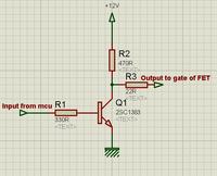
80N70, 75N75 or IRF3205 are common and available all over pakistan. Use any of one of them but use a transistor based driver to operate. This is a simple driver. Logic is inverted so immediately after power on set mcu pin high to stop power to solenoid.
 
.............................
This is what you should look for:

Id rating > 5A
Vds rating > 24V
Vgs rating > 24V
Vth < the voltage you are driving it from (the microcontroller output voltage).

.........................
When using a MOSFET at a switch it's not he Vth (threshold) voltage you should look at but the Vgs used when the Rds ON resistance value is measured. That is the voltage you need to fully turn on the MOSFET, not Vth. Vth is the voltage where the MOSFET is just starting to turn on.

For driving from a logic signal you need to use a Logic-Level type MOSFET where the Rds ON is measured with a Vgs of 5V (or sometimes 3V). Standard MOSFETs have the Rds ON measured with a Vgs of 10V and won't work well as a switch with a Vgs of 5V.
 
Status
Not open for further replies.

Similar threads

Part and Inventory Search

Welcome to EDABoard.com

Sponsor

Back
Top