Continue to Site

Welcome to EDAboard.com

Welcome to our site! EDAboard.com is an international Electronics Discussion Forum focused on EDA software, circuits, schematics, books, theory, papers, asic, pld, 8051, DSP, Network, RF, Analog Design, PCB, Service Manuals... and a whole lot more! To participate you need to register. Registration is free. Click here to register now.

Timer that powers off after cycle (555?)

Status
Not open for further replies.

DOD

Newbie level 3
Joined
May 28, 2014
Messages
4
Helped
0
Reputation
0
Reaction score
0
Trophy points
1
Activity points
33
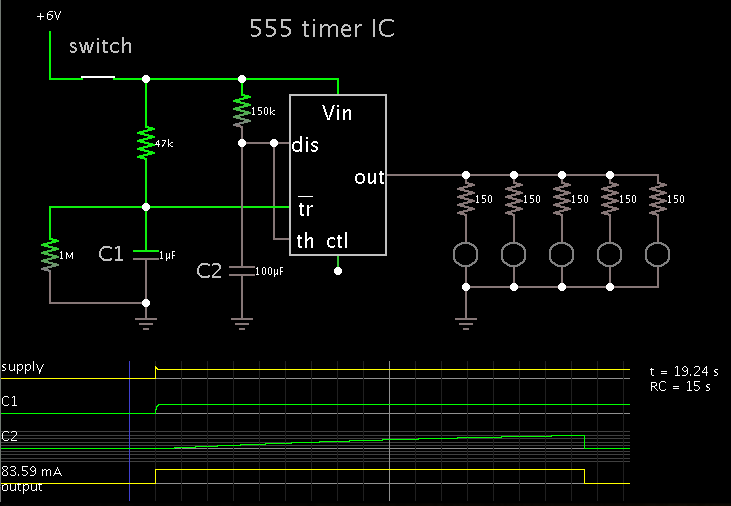
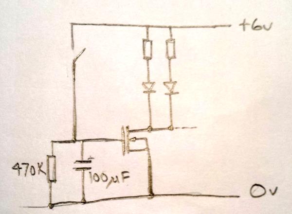
I am building a battery powered device (preferably 6v from 4xAA’s) that will drive about 5-10 bright LED’s for 10-15 seconds when a door is opened.
When LED’s power off I would like power to be automatically disconnected altogether so there is zero residual current.

There should be a trigger that restarts the timer (can be the same trigger that starts it in the beginning), but the idea is to completely disconnect power when not in use to maximize battery life.

I understand that the cmos 555 draws only about 110ua in standby, but this device will need to sit idle for days at a time waiting for a trigger. I want the battery replacement time to be measured in months or years, rather than weeks.

I have scoured the web for suggestions but come up empty handed.

Can anyone suggest a circuit for me?
 

- Use small footprint 555 IC's which are for low power application like CSS555S, TLC555, LMC555.
- If using above IC's already, run 555 power at 2V or smaller supply which will reduce the power to few uA. For this dc-dc charge pump step down regulator can also be used as in here: https://www.microchip.com/ParamChartSearch/chart.aspx?branchID=9006&mid=10&lang=en . It works without inductor and leakage is very low. Good for battery applications.
- Use a microcontroller like any PIC12Fxxxx device, it takes 20nA at 2V running at 32kHz to 500kHz in sleep mode which is good enough for your application. Obviously to run at this low voltage a charge pump dc-dc convertor or switching regulator should be used. If watchdog is used for periodic checking 300nA is max current used. In most cases, the current does not exceed few micro amperes.
- Or you can also use a mechanical normally-ON relay which is supply 555 IC when door is open. As soon as door is closed, the magnet in door will activate relay to OFF state. And power to 555 and IC will cut down. (assuming the relay is installed on door rails but not on door and magnet installed on door.

Hope that helps.
 

You can probably do this even simpler with switch (reed relay/magnet?) and an RC network in the gate of a small power MOSFET. The LEDs might dim for the final fraction of a second but the leakage current would be negligible.

Brian.
 

Thanks ashugtiwari and betwixt.
I should have mentioned that this needs to be low cost, small and simple.

Betwixt, are you able to suggest a circuit diagram I might try?

My tech skills and understanding are moderate so simple works for me :).
 

Simulation showing how a switch can power a 555.

The switch should be a SPDT type, wired so it is open when the door is shut.

The leftmost RC network ensures the trigger pin will be pulled low momentarily at power-up.


This gives about 15 seconds of light, it does dim down at the end before going out completely but stays at full brightness most of the time. I checked it with an IRF530 MOSFET and 6V supply and when off I could not measure any current at all, the DVM I used is good to about 0.1uA.

The switch closes to turn the light on and it stays on for about 15 seconds after it has opened again. I can't think of a simpler circuit.

Brian.
 

Perfect Betwixt. Thanks!
I will give it a go.

What value would you use for the LED resistor for a simple white 5mm LED?
I am also presuming to shorten the "On" time I just need to reduce the value of either of the RC network?
 
Last edited:

relay_app_1.png
Here, the door is open so, magnet is not near mechanical relay to switch it OFF and its normally-ON relay.

relay_app_2.png
Here, the door is closed and magnet is in line and near to mechanical relay which will switch it OFF and no power supply to 555 circuit.

Hope that helps.
 

Not so sure ashugtiwari.
If the door is left open after the LED has timed out, the 555 is still held under power.
I need the timer to disconnect from power after its cycle.
 

The resistor values are calculated by:
(Supply voltage - LED forward Voltage) / LED current.

So with a 6V supply and a guess at 3V for the LED Vf and say 20mA (get the exact values from the LED data sheet) the resistor in each LED should be:
(6 - 3)/0.02 = 150 Ohms. Use one resistor per LED but you can join many in parallel between the MOSFET drain and the supply.

You can adjust the time before it turns off by changing the resistor and capacitor values. Higher capacitor value = longer, higher value resistor = longer.
You can make it variable by using a potentiometer (1M would be a good starting value) but if you do that, also wire a 10K fixed resistor in series with it so that when it is set at low value and the switch is closed, it doesn't let too much current through.

Brian.
 

Status
Not open for further replies.

Part and Inventory Search

Welcome to EDABoard.com

Sponsor

Back
Top