Continue to Site

Welcome to EDAboard.com

Welcome to our site! EDAboard.com is an international Electronics Discussion Forum focused on EDA software, circuits, schematics, books, theory, papers, asic, pld, 8051, DSP, Network, RF, Analog Design, PCB, Service Manuals... and a whole lot more! To participate you need to register. Registration is free. Click here to register now.

Timer relay question! Help needed please.

Status
Not open for further replies.
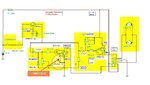
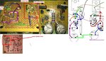
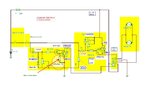
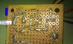
I need a better picture from the solder side to check the connections. Meanwhile try to adjust the pots, turn each one in order to obtain some ‘ middle position’ adjustment, there’s a possibility to have one left for zero value.
 

So, I need more details in the marked area.
 

Attachments

  • checking solder side.JPG
    checking solder side.JPG
    249.9 KB · Views: 69

I did more work to the board after the previous pictures were taken. These are recent pictures of the board: IMAG0181.jpg IMAG0182.jpg IMAG0186.jpg IMAG0187.jpg
 

Got it! It was the pot connection you pointed out. GOOD EYES!!! Once again you have proven yourself to be "The Man"!!! Thanks again!!! Going to try and find a case for everything. I so psyched about this mod!!!
 

Have you changed any component position on the PCB?

---------- Post added at 23:08 ---------- Previous post was at 23:06 ----------

OK, I'm glad problems solved.
 

Hey, mister_rf. I hope all is well with u. I just got around to connecting the mirror and timer. I had to have some body work done to the truck and just got it completed. I couldn't find a switched power source in the door. So, I have both power wires hooked up to constant, and control fold/extend with a SPST switch. However, the values keep fluxuating and the time duration will not remain constant, so I may have to use a fixed value resistor instead of a POT. I was making adjustments for about an hour. The weird problem is that, in one direction (when the relay closes), the relay buzzes like a piezoelectric buzzer, when the time interval is complete (after the mirror reaches its extended position). Now the mirrors will not fold at all anymore, even though I can hear the relay click. I even noticed that when I rev the engine, it will make the relay buzz! Its really weird... Any ideas and possible solutions to these issues???
 

Need to consider first to replace pots with some fixed resistors ( 2.2k up to 4.7k). Test the circuit after components are replaced.
 

I thought about trying that. But I won't get a chance to revamp the circuit until mid October. Got a big project coming up then vacation. I was working on the mirrors all evening today. Just discovered that the driver mirror takes twice as long to fold out as the passenger mirror. I think the circuit damaged the mirror motor. I'm going to try and have it replaced under warranty but I tinkered with it so I don't know if that's going to work. I was wondering if the relay is suffering from "contact bounce". And that the relay chatters during engine revs because the alternator voltage is fluctuating. If this is the case, I'm wondering if a solid state DPDT relay will solve the problem. I may just have to revert to my original plan with the 2 timer relays. I also thought about hooking the mirrors up in series to match motor speeds when folding/extending.
 

Ok. My project ended sooner than planned so I got a chance to revamp the circuit. I replaced the POTS with a 1k resistor. The timing is good but I still have the same relay chatter problem. Once again I'm lost as to what to do next. HELP!!!
 

Let's try first to add a resistor in the circuit, see the diagram.
 

Attachments

  • Auto%20DPDT%20relayx.JPG
    Auto%20DPDT%20relayx.JPG
    159 KB · Views: 61
  • IMAG0186_a.jpg
    IMAG0186_a.jpg
    184.7 KB · Views: 62

As a next step we can try to insert a NPN transistor to smooth the voltage. :)
 

Attachments

  • Auto folding version 3.JPG
    Auto folding version 3.JPG
    174 KB · Views: 61

Ok. But i don't see a diagram...

---------- Post added at 14:04 ---------- Previous post was at 14:03 ----------

Ok. I needed to sign in first. I see it now.
 

Ummmm, can you show me the last 2 circuit connections with diagrams like the one in post #117 please?
 

OK.
First diagram include the supplementary resistor.(470 ohms).

Second include also some voltage stabiliser =1 NPN (power transistor TIP3055) + 1 zenner diode (12V) + 1 electrolytic capacitor (100uF/25V) + 1 resistor (470 ohms).
 

Attachments

  • Timer%20fix%20resistor2.JPG
    Timer%20fix%20resistor2.JPG
    86.1 KB · Views: 63
  • Timer vers 3.JPG
    Timer vers 3.JPG
    102.4 KB · Views: 61

You are a genius!!!! I may have to start calling you "The Wizard"!!! The circuit works pretty great now. No chatter. Just smooth folding and extension!!! Only problem is that the mirrors sometimes half extend/fold when the windows are rolled down. Or sometimes they half extend, fold, then extend again when the vehicle is first started. I'm thinking the power fluctuations are causing the problem, and that they need a brief delay period when power is applied to the circuit to sort out whether the circuit is being charged/discharged deliberately. Is there a way to build this safeguard into the circuit???
 

Hey mister_rf. Hope everything is good with you. I just wanted to ask if you had any thoughts on my last post? Concerning the half extend/fold situation. The mirrors seem to do it capriciously. With no apparent triggers sometimes. But I'm pretty sure it's due to some type of variant power fluctuation. I think an extend/fold delay would rectify the problem, but you are the expert in these matters. Is there something I can do about this?
 

Hey mister_rf. Happy New Year. You never replied to my last post and I'm still experiencing the problem. Do you have any suggestions that may help resolve it?
 

Status
Not open for further replies.

Part and Inventory Search

Welcome to EDABoard.com

Sponsor

Back
Top