mcmsat13
Member level 5

- Joined
- Apr 24, 2013
- Messages
- 94
- Helped
- 4
- Reputation
- 8
- Reaction score
- 4
- Trophy points
- 1,288
- Activity points
- 2,292
The circuits below are simulation circuits for my SCR H-bridge driver with passives and discrete components.
I have have been looking for a way to drive thyristors/SCRs in DC applications but gating the devices, especially turning them off has been a poser to me. I have Googled for a standard driver circuit regarding this constraint and only saw little or no circuit relating to my application.
I know there are people here who are experts in electronic designs.
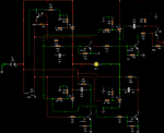
The circuit below shows when the switch is in mode A; the SCR D1 and D3 are switched on while D2 and D4 are turned off
The switch at mode B; the SCR D2 and D4 are switched on while D1 and D3 turned off.
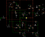
Now, the circuit with a motor, switch in mode A If I turn the circuit on, it worked in any of the mode; A or B but if I switch from one mode to another then something bad happen!
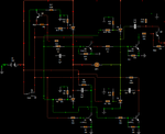
With Motor, switch in mode B:
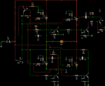
The circuit below shows when I switch to another mode.
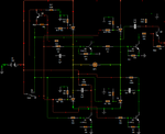
Please I want your help here. this circuit I have been looking for but I could not see any. I design this circuit through thyristor theories base on Forced Capacitor forced commutation, C1 to C4.
I just design this but i know that there is something I am missing or some values that are underrated or overrated. Please I want some corrections in this circuit.
I have have been looking for a way to drive thyristors/SCRs in DC applications but gating the devices, especially turning them off has been a poser to me. I have Googled for a standard driver circuit regarding this constraint and only saw little or no circuit relating to my application.
I know there are people here who are experts in electronic designs.
The circuit below shows when the switch is in mode A; the SCR D1 and D3 are switched on while D2 and D4 are turned off

The switch at mode B; the SCR D2 and D4 are switched on while D1 and D3 turned off.

Now, the circuit with a motor, switch in mode A If I turn the circuit on, it worked in any of the mode; A or B but if I switch from one mode to another then something bad happen!

With Motor, switch in mode B:

The circuit below shows when I switch to another mode.

Please I want your help here. this circuit I have been looking for but I could not see any. I design this circuit through thyristor theories base on Forced Capacitor forced commutation, C1 to C4.
I just design this but i know that there is something I am missing or some values that are underrated or overrated. Please I want some corrections in this circuit.

