lee321987
Member level 5
Hello.
I've just breadboarded a battery charger based on the MAX713 IC -- datasheet: **broken link removed**
It's working but I'm not sure how to set up the thermistors.
I purchased some 100K@25C NTC thremistors.
Now I have to choose values for R3,R4,R5.
Any help?
Here is the relevant paragraph and image from page 12-13 of the datasheet (the diagram on page 1 doesn't use temperature to cut-off charge current):
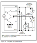
Figure 9a shows how the MAX712/MAX713 detect over-
and under-temperature battery conditions using negative
temperature coefficient thermistors. Use the same model
thermistor for T1 and T2 so that both have the same
nominal resistance. The voltage at TEMP is 1V (referred
to BATT-) when the battery is at ambient temperature.
The threshold chosen for THI sets the point at which
fast charging terminates. As soon as the voltage-on
TEMP rises above THI, fast charge ends, and does not
restart after TEMP falls below THI.
The threshold chosen for TLO determines the tem-
perature below which fast charging will be inhibited.
If TLO > TEMP when the MAX712/MAX713 start up, fast
charge will not start until TLO goes below TEMP.
[....]
All resistance values in Figures 9a
and 9b should be chosen in the 10kΩ to 500kΩ range.