Continue to Site

Welcome to EDAboard.com

Welcome to our site! EDAboard.com is an international Electronics Discussion Forum focused on EDA software, circuits, schematics, books, theory, papers, asic, pld, 8051, DSP, Network, RF, Analog Design, PCB, Service Manuals... and a whole lot more! To participate you need to register. Registration is free. Click here to register now.

thermal simulation on microwave test circuit

Status
Not open for further replies.

mohamis288

Full Member level 3
Joined
Mar 1, 2022
Messages
164
Helped
0
Reputation
0
Reaction score
1
Trophy points
18
Activity points
1,235
Hi,
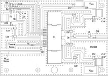
I want to simulate and test a RF IC. its large signal model without layout is available on the producer website. how can I do thermal simulation on this IC? no further file is available except that large signal model. in fact, I want to do thermal simulation on the test circuit which uses this IC. I have attached the microwave test circuit schematic.
 

Attachments

  • Screenshot (115)_LI.jpg
    Screenshot (115)_LI.jpg
    256.7 KB · Views: 193

It's generally difficult to predict thermal response of such application circuit because you don't know all the details about package, substrate, heatsink etc. RFIC or MMIC circuits are easier for predicting thermal effect because almost all layer specifications are readily available.
All you can do is to measure the thermal vision of the board.
 

Hi, BigBoss
thank you for your response.
well I have some clues. I have attached two images in the following. I have performed Co-simulation on the test circuit which was available in the datasheet. now, I continue simulations in schematic window.
as you can see in the "self thermal" image, there is one feature in IC property in ADS which apparently provides thermal feature.
also, in the "thermal lead" image, you can see two leads connected to the IC which apparently help two do thermal simulation.
but we do not have any tutorials on how to perform thermal simulation. for example, there nothing said on datasheet about what we should connect to thermal leads in the IC. there is nothing in datasheet or producer company.
have you any similar experiences working with such ICs or have you any advice to perform thermal analyses?
 

Attachments

  • self thermal.png
    self thermal.png
    22.3 KB · Views: 179
  • thermal lead.png
    thermal lead.png
    41.3 KB · Views: 182

It's generally difficult to predict thermal response of such application circuit because you don't know all the details about package, substrate, heatsink etc. RFIC or MMIC circuits are easier for predicting thermal effect because almost all layer specifications are readily available.
All you can do is to measure the thermal vision of the board.
Hi, @BigBoss
thank you for your response.
well I have some clues. I have attached two images in the following. I have performed Co-simulation on the test circuit which was available in the datasheet. now, I continue simulations in schematic window.
as you can see in the "self thermal" image, there is one feature in IC property in ADS which apparently provides thermal feature.
also, in the "thermal lead" image, you can see two leads connected to the IC which apparently help two do thermal simulation.
but we do not have any tutorials on how to perform thermal simulation. for example, there nothing said on datasheet about what we should connect to thermal leads in the IC. there is nothing in datasheet or producer company.
have you any similar experiences working with such ICs or have you any advice to perform thermal analyses?
 

Attachments

  • self thermal.png
    self thermal.png
    22.3 KB · Views: 179
  • thermal lead.png
    thermal lead.png
    41.3 KB · Views: 177

Status
Not open for further replies.

Similar threads

Part and Inventory Search

Welcome to EDABoard.com

Sponsor

Back
Top