Continue to Site

Welcome to EDAboard.com

Welcome to our site! EDAboard.com is an international Electronics Discussion Forum focused on EDA software, circuits, schematics, books, theory, papers, asic, pld, 8051, DSP, Network, RF, Analog Design, PCB, Service Manuals... and a whole lot more! To participate you need to register. Registration is free. Click here to register now.

Thermal Analysis: TPS7A4501KTTR

engr_joni_ee

Advanced Member level 3
Joined
Nov 3, 2018
Messages
750
Helped
2
Reputation
4
Reaction score
4
Trophy points
18
Activity points
6,229
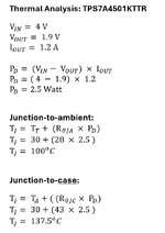
I did calculation for thermal analysis of TPS7A4501KTTR.
I am not sure which thermal resistance should I use in formula, junction-to-case or junction-to-ambient ?

If I use thermal resistance junction-to-case (43 C) then I get junction temperature = 137 C and
if I use thermal resistance junction-to-ambient (28 C) then I get junction temperature = 100 C.

Untitled 608.png
 
Hi,

in the "junction" heat becomes generated.

1) now you did the first step correctly to calculate the power dissipation.

2) Then do the next step - calculate without any additional cooling effort - just to dissipate the heat directly to the ambient.

***
If you now see that the junction temperature is too high, then you need additional effort to spread the heat.
This could be via the PCB, via heatsink, via increased air flow (fan) ...

So:
junction -> package --> heat spreader --> ambient

or more detailed:
Junction --> package, legs --> PCB, copper --> ambient
Junction --> package --> heatsink --> ambient

Klaus
 
Thanks for the explaination. It help a lot to understand the concept.

I am not sure if I get point number 2. You mentioned, "calculate without any additional cooling effort - just to dissipate the heat directly to the ambient." I guess the calculation in point 1 is already without any additional heat sink.
 
If you are measuring case temp then use thetaJC. But realize that in
plastic packaging especially, top face temp is going to be somewhere
between bottom face / leadframe temp and ambient. The shortest
bond wire length and distance-to-die will be closest to junction temp.
Package mold compound is just not a great conductor of heat.

If you can find an unburdened input or output pin, to force a test
current onto, then you could directly measure die temp by diode Vf
to temperature correlation, and then you would know for sure the
junction temp and which of the environmental "goalposts" you are
really closest to. Might need to jig up specially to control load,
power and test access. And of course pull the Vf - temp data.
 
I am not sure if I get point number 2. You mentioned, "calculate without any additional cooling effort - just to dissipate the heat directly to the ambient." I guess the calculation in point 1 is already without any additional heat sink.
sorry for not being clear:

1) is just calculation of power dissipation
2) is temperature (rise) calculation // according power disspation and R_th_ja

Klaus
 

    FvM

    Points: 2
    Helpful Answer Positive Rating
Thanks. According to datasheet.
R_th_ja (Junction-to-ambient thermal resistance) = 28 degC
R_th_jc (Junction-to-case (top) thermal resistance) = 43 degC

My calculations are:

Junction-to-ambient temperature = 100 degC
Junction-to-case top temperature = 137 degC

The detail of calculations is also attached. I guess these numbers are without any heatsink, right ?

Datasheet says: operating junction temperature range = -40 degC to +125 degC.

Do I need any cooling or heat sink ?
 

Attachments

  • Untitled 608.png
    Untitled 608.png
    23.3 KB · Views: 38
I am not used to seeing JA less than JC. To me this indicates
that the main thermal exit path is through the leads (and any
underfill) so not really a thetaJA physical configuration in my
book.

Or some marketing tool just swapped values when they
prettied up the datasheet, can't rule that one out.

Still recommend an effort to measure, if you have the
physical article and the equipment.
 
Hi,

I agree with the others that R_TH_JC smaller than R_TH_JA makes not much sense.

Anyways: Neither of the two package varaints are designed for a heatspreader mounted on the top of the case (what R_TH_JC is used for).
Thus I think one can simply ignore the R_TH_JC value.

Either use it without heatsink --> R_TH_JA
or use with a suitable PCB board layout to spread the heat --> R_TH_JB

******
Did you read the "thermal information" chapter in the datsheet?
Especially:
(1) For more information about traditional and new thermal metrics, see the Semiconductor and IC Package Thermal Metrics application
report, SPRA953.
(2) For thermal estimates of this device based on PCB copper area, see the TI PCB Thermal Calculator.


--> They even give links to the according informations. How much more easier for you can they make it?

You repeatedly ask questions about heat spreading ... while you simply have to follow their links.

Klaus
 
The datasheet spec makes pretty sense, but you need to read and understand it. Quoted 43 K/W number is junction to case  top, not junction to case. Very unlikely that this spec is relevant for your application.

Junction-to-ambient is describing typical application cases, but it's presuming certain PCB size. If you had read datasheet up to page 25, the guesses in post #1 and #3 are obsolete.
 
I just read the following three articles to understand thermal analysis in linear regulators.


LaTeX Commands Quick-Menu:

Similar threads

Part and Inventory Search

Welcome to EDABoard.com

Sponsor

Back
Top