Continue to Site

Welcome to EDAboard.com

Welcome to our site! EDAboard.com is an international Electronics Discussion Forum focused on EDA software, circuits, schematics, books, theory, papers, asic, pld, 8051, DSP, Network, RF, Analog Design, PCB, Service Manuals... and a whole lot more! To participate you need to register. Registration is free. Click here to register now.

Thermal analysis - LDO regulator

engr_joni_ee

Advanced Member level 3
Joined
Nov 3, 2018
Messages
750
Helped
2
Reputation
4
Reaction score
4
Trophy points
18
Activity points
6,229
I am trying to understand the thermal analysis especially how to calculate junction temperature. I will ask my question but I am wondering how do we write mathematical symbols or equations here in the editor ?

I was reading the datasheet of MIC29302A. In the data sheet on page 10 (see attachment) they use maximum ambient temperature 75C and not 25C. I don't get it. I guess the ambient temperature is 25C which is like room temperature but they use 75C.

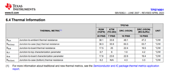
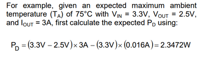
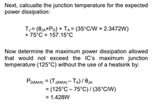
On page 11 (see attachment), the have found junction temperature 157 C which is outside the operating range. So, in order to calculate junction temperature (T_J), we need out maximum power dissipation (P_D), ambient temperature (T_A) and also package thermal resistance (theta_J-A), right ? And the junction temperature (T_J) should be within the operating thermal range, right ?
 

Attachments

  • Untitled 584.png
    Untitled 584.png
    27.2 KB · Views: 59
  • Untitled 585.png
    Untitled 585.png
    46.1 KB · Views: 59
Last edited:
But is that true, in order to calculate junction temperature (T_J), we need maximum power dissipation (P_D), ambient temperature (T_A) and also package thermal resistance (theta_J-A). And the junction temperature (T_J) should be within the operating thermal range ?
--- Updated ---

Sorry I was not able to write maths symbols. Kindly let me know how do we write maths symbols and equations here in the editor. Thanks in advance.
 
Yes, we need to get to the worst case Tj we need to know either
Ta or Tc and associated theta's in the path to the junction, from
the ambient/reference T was taken. And of course the power we
will be dissipating.


Thermal Calculator :


Regards, Dana.
 
Sorry I was not able to write maths symbols. Kindly let me know how do we write maths symbols and equations here in the editor.
The editor window has this button [three vertical dots in a row] = "more options"
And below the text field there is the [LATEX Commands Quick-Menu]

Klaus
 
Now I manage to write the equation using LaTex commands.

In the given example in the original post. They have calculated the junction temperature which is 157.15 C. They use the parameters thermal resistance, power dissipation, and the ambient temperature and found the junction temperature is exceeding the IC maximum allowed junction temperature, right ?
But all this is without the use of heat sink. How we can add/include the effect of heat sink in the calculations ?


--- Updated ---

Yes, we need to get to the worst case Tj we need to know either
Ta or Tc and associated theta's in the path to the junction, from
the ambient/reference T was taken. And of course the power we
will be dissipating.


Thermal Calculator :


Regards, Dana.
Hi Dana, how are explain Ta and Tc. I guess Ta is ambient temperature but what is Tc ?
 
Last edited:
Google "Thermal calculator heatsink"

Tc = Tcase.

Regards, Dana.
 
Last edited:
ThetaJA is a number obtained under specific conditions. A
different board layout, a different airflow / shrouding if the
air path for heat outflow is indeed a significant portion, and
your "air" then is different and so is the thermal impedance.

ThetaJA is an upper bound to crappiness under the electrical
conditions. But nobody suspends parts in air (except to test).
ThetaJC is the lower bound. What you put between case and
ambient air (and what shares it) makes all the difference.

If you want real, you have to measure a real article under
your real worst case condition. It's not that hard to do. Then
you will know where you really stand.
 
I am sorry. I am bit confuse again. I found another LDO "TPS74901" which is 3 A voltage regulator with thermal information given in section 6.4.

There are three packages.
DRC 10-Pin VSON
RGW 20-Pin VQFN
KTW 7-Pin DDPAK/TO-263

According to section 6.3, the operating junction temperature is between -40 C to +125 C.

If Vin = 3.3 V and Vout = 1.9 V. The current load is 1.2 A. Do I need any heat sink. How can I calculate maximum junction temperature for the KTW 7-Pin DDPAK/TO-263.
 

Attachments

  • Untitled 596.png
    Untitled 596.png
    102.9 KB · Views: 97
Hi,

there quite a lot of good application notes out there, giving good insight and knowledge how to judge on the given boundary conditions e.g. [1]. Even the document linked in the footnote of table 6.4 will answer your question [2] (section 1.8). For the TPS74901 the +125°C is the recommended maximum junction temperature, the absolute maximum is +150°C. The TPS74901 even has a thermal protection, see section 7.3.4.

To determine/estimate your junction temperature, the maximum expected ambient temperature is of interest. Further, the layout has a huge impact by means of effective copper area which helps to distribute the heate, see section 8.4.1.2 and especially Figure 8-9.

[1] https://fscdn.rohm.com/en/products/...ulator/linearreg_heat_calculation_appli-e.pdf
[2] https://www.ti.com/lit/an/spra953c/spra953c.pdf?ts=1707464886459

BR
 
Do you need a heatsink for 1.17W on a TO-263 7pin?
Yes

  • But how you do that depends on Ta and Tj max margin you choose for reliability overall and how much sinking can be done on PCB.
  • Compare with a resistor which can handle higher Tj's but can also degrade reliability of e-caps nearby from T rise.

  • Assume the resistor junction temp rise is shown in the plot with Pd [%] vs T ['C]
  • Now compute the Rja= (Tmax-Tknee) / Pmax
  • For a 1/2 W resistor Rja = 170 'C/W = 85/0.5

1707574338818.png


  • Most IC's are rated with a std. PCB 2S 2oz _sq.cm heatsink for Rja, unlike a vertical mount in air inside an enclosure which will be much higher.
    • See chart below that compares -ve% shift in Rja from 1 to 2 sided copper heatsinks.
  • In this former case (no pun intended) you could compare that with a resistor of similar area.
  • Also THT resistors have slight different Rja ratings depending on mounting orientation and lead-length in convection air.
1707575478620.png


Your recent question

If Vin = 3.3 V and Vout = 1.9 V. The current load is 1.2 A. Do I need any heat sink. How can I calculate maximum junction temperature for the KTW 7-Pin DDPAK/TO-263.

My design criteria
1. Decide how much heat rise sharing you want to avoid to caps and other thermal sensitive parts and isolation required.
2. Choose a reliable margin by derating the Trise = Pmax*Rja by 50% as a starting point.
50% of recommended Tj max = 125'C or a 100'C rise above 25'C thus Tj max = 75'C for a starting point.​
3. Compute Power Pd = Vio*I = (3.3-1.9)*1.2 = 1.17W Thus solve for Rja
Tj =Ta + Rja*Pd above ambient​
If Ta= 25'C then Rja=(75-25'C)/1.17W = 42.7'C​
Most of your heatsink on the stds below is done by the Cu on PCB but that is often 1sqin/W 2S*2oz or 6.5 cm^2 which is large and expensive for 2oz for 2S in volume.​
But since the datasheet below is better than required, you may be able to use or reduce the size of the PCB CU heatsink. A thermal insulator to a metal case might be cheaper solution.​

untitled-596-png.188428


Caveat Emptor

In fact, in still-air JEDEC-defined RθJA measurements,
almost 70%–95% of the power generated by the chip is dissipated from the test board, not from the
surfaces of the package. Because a system board rarely approximates the test coupon used to determine
RθJA, application of RθJA using Equation 1 results in extremely erroneous values.

1707577710376.png


I hope this adds useful info.

regards,
Tony

p.s. off the cuff, for those interested in e-cap MTBF, note that they are rated for something like hours of mean time between failures for a time rating at some temp. like 3kh at 85 or 115'C. This comes from self heating + Tambient. Then Arrhenius Law rules for reliability are typically 50% per 10'C rise. Thus working backwards every 10'C rise in temperature rise above ambient, you can estimate the mean lifespan. Extreme cold temp.'s may have other failure mechanisms in e-caps dependng on product. But the takeaway is don't heat up high Irms stressed caps near hot parts. ( although for LDO's one doesn't expect a lot of rms current.)
 
Last edited:
When you decide to depend on board copper for heat removal
you also must include the heat load from neighbors into same.
LDO heat may be matched or exceeded by its "clients" which
may tend to be co-located, depending on internal drop vs
Vout. The "L" in LDO inplies that you'd be trying to dissipate
as little internally as possible, so local heating of the "sink
plane" may not be represented well looking at the LDO alone,
sitting in a sea of copper.
 

LaTeX Commands Quick-Menu:

Similar threads

Part and Inventory Search

Welcome to EDABoard.com

Sponsor

Back
Top