Continue to Site

Welcome to EDAboard.com

Welcome to our site! EDAboard.com is an international Electronics Discussion Forum focused on EDA software, circuits, schematics, books, theory, papers, asic, pld, 8051, DSP, Network, RF, Analog Design, PCB, Service Manuals... and a whole lot more! To participate you need to register. Registration is free. Click here to register now.

The simplest FM transmitter and receiver module

Status
Not open for further replies.

Eshal

Advanced Member level 1
Joined
Aug 29, 2012
Messages
470
Helped
16
Reputation
32
Reaction score
15
Trophy points
1,298
Location
Nowhere :)
Activity points
5,149
Hello to all again

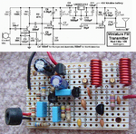
I want to design my own FM transmitter and receiver module, the most simplest one so that I could understand it and its designing.

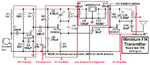
Here is the block diagram of FM transmitter
Transmitter block diagram.PNG

First we should design an audio oscillator. Right? So anyone can help me in designing that circuit which can generate frequency from 20Hz to 20kHz?

First this circuit then I will move forward to the 2nd block of the block diagram.

Thank you all.
 

??? There is no audio oscillator in that design!

FM transmitters have a trade off between cost and quality. The simplest transmitter could be nothing more than a single transistor RF oscillator with the microphone audio fed into it but it wouldn't work very well and would be prone to drifting in frequency with temperature, voltage and even proximity to other objects, including yourself!

What frequency are you planning to use? I presume you want it to be heard up on a normal domestic FM radio but in theory you can use almost any frequency as long as you have a matching receiver to pick it up.

Brian.
 
  • Like
Reactions: Eshal

    Eshal

    Points: 2
    Helpful Answer Positive Rating
In most countries it is illegal to cause interference with radio stations. So the maximum allowed output power is fairly low and a power amplifier cannot be used without having the licence for a radio station.

A transmitter does not use an audio oscillator, instead it uses a microphone preamplifier. To reduce hiss, FM radio stations boost high audio frequencies (pre-emphasis) and FM receivers cut the high frequencies (de-emphasis) back down to normal which reduces hiss. Most simple FM transmitter projects do not have pre-emphasis so the de-emphasis in FM receivers cuts the high audio frequencies which makes the sound muffled like your stereo with its treble tone control turned all the way down.

Somebody on another website posted an FM transmitter that didn't work. I built it and saw 4 things wrong with it. I fixed each problem separately and I call my fixed FM transmitter Mod 4 because I modified it 4 times:
1) Its mic preamp did not work when the 9V battery was new and also did not work when the battery was old. I fixed its biasing.
2) The radio frequency changed as the battery voltage ran down. I added a small low dropout 5V voltage regulator.
3) Its frequency changed if something moved towards or away from its antenna. I added an RF amplifier to separate its RF oscillator from its antenna.
4) It sounded muffled like an AM radio so I added pre-emphasis.

It sounds great like a real FM radio station. If it is tuned to the same frequency as a distant radio station it can cause interference but its output power is not high.
Mine has a range of more than 2km to a very sensitive (expensive) hi-fi tuner and car radio over a huge river valley with nothing in between. Its range is about 400m to my cheap Sony Walkman FM portable radio. Its range is across the street to a cheap clock radio.

I made mine on stripboard with a compact layout. The strips were cut with a drill bit so that each strip of copper was used for a few different conductors. The strips formed half of a pcb wiring and the parts and a few jumper wires formed the other half.

Here it is:
 

Attachments

  • FM transmitter pic + schem.PNG
    FM transmitter pic + schem.PNG
    195.9 KB · Views: 176
  • Like
Reactions: Eshal

    Eshal

    Points: 2
    Helpful Answer Positive Rating
@betwixt
??? There is no audio oscillator in that design!
By audio oscillator I meant to be the audio amplifier, the first block in the FM transmitter. Of course, we need first audio oscillator then an audio amplifier. Actually, I am not using mic instead I am using audio oscillator to generate same frequency as human voice between 20Hz and 20kHz. Now you get an idea sir what is my meant by audio oscillator?

FM transmitters have a trade off between cost and quality. The simplest transmitter could be nothing more than a single transistor RF oscillator with the microphone audio fed into it but it wouldn't work very well and would be prone to drifting in frequency with temperature, voltage and even proximity to other objects, including yourself!
Yes sir, I am aware of this.

What frequency are you planning to use? I presume you want it to be heard up on a normal domestic FM radio but in theory you can use almost any frequency as long as you have a matching receiver to pick it up.
Yes, to be heard upon a normal domestic FM radio. In any empty band. If no band is free then I will switch to the frequency.

audioguru
In most countries it is illegal to cause interference with radio stations. So the maximum allowed output power is fairly low and a power amplifier cannot be used without having the licence for a radio station.
Sir, I know FCC rules as I had subject "Electronic Communication" during my electronics degree. So I will be beware of this. I just want to make low power so that no interference could examined.

A transmitter does not use an audio oscillator, instead it uses a microphone preamplifier. To reduce hiss, FM radio stations boost high audio frequencies (pre-emphasis) and FM receivers cut the high frequencies (de-emphasis) back down to normal which reduces hiss. Most simple FM transmitter projects do not have pre-emphasis so the de-emphasis in FM receivers cuts the high audio frequencies which makes the sound muffled like your stereo with its treble tone control turned all the way down.
Yes sir, so I will not include pre-emphasis and de-emphasis design in my FM transmitter. As I will learn this simple then I will move to complex.

Somebody on another website posted an FM transmitter that didn't work. I built it and saw 4 things wrong with it. I fixed each problem separately and I call my fixed FM transmitter Mod 4 because I modified it 4 times:
1) Its mic preamp did not work when the 9V battery was new and also did not work when the battery was old. I fixed its biasing.
2) The radio frequency changed as the battery voltage ran down. I added a small low dropout 5V voltage regulator.
3) Its frequency changed if something moved towards or away from its antenna. I added an RF amplifier to separate its RF oscillator from its antenna.
4) It sounded muffled like an AM radio so I added pre-emphasis.
OMG... You are a real electronic engineer. I want to be just like you that recognize and correct the problems as you did. Will you transfer your knowledge to me sir?

It sounds great like a real FM radio station. If it is tuned to the same frequency as a distant radio station it can cause interference but its output power is not high.
Mine has a range of more than 2km to a very sensitive (expensive) hi-fi tuner and car radio over a huge river valley with nothing in between. Its range is about 400m to my cheap Sony Walkman FM portable radio. Its range is across the street to a cheap clock radio.

I made mine on stripboard with a compact layout. The strips were cut with a drill bit so that each strip of copper was used for a few different conductors. The strips formed half of a pcb wiring and the parts and a few jumper wires formed the other half.
Is your transmitter range 2km or 400m? And what is the output power of it?

Dear audioguru sir, can you please separate each and every circuit in your design like pre-emphasis, RF oscillator block, AF amplifier block, etc... ?

Thank you both of you.
 

The frequency response of a good FM broadcast radio transmitter and receiver is supposed to be from 50Hz to 15kHz but some radio stations transmit deep bass sounds down to 20Hz. The FM stereo transmitter cuts sounds above 15khz so that they do not beat with the 19kHz stereo pilot tone. The FM receiver cuts frequencies above 15kHz so that the stereo pilot tone at 19kHz is not heard.

A cheap FM radio might produce sounds from 300Hz to 6kHz.

You can attenuate an audio oscillator down to mic level, remove R1 that powers an electret mic and test the transmitter and receiver levels if you want.

EDIT: I forgot to say that the range depends on the sensitivity of the FM receiver. The output power of my FM transmitter is about 25mW (0.025W).

I marked a few of the blocks in my FM transmitter:
 

Attachments

  • FM tx Mod4 blocks.png
    FM tx Mod4 blocks.png
    58 KB · Views: 125
  • Like
Reactions: Eshal

    Eshal

    Points: 2
    Helpful Answer Positive Rating
OK thank you sir.
But your transmitter doesn't have blocks like my block diagram in the post#1. Like, where is AF amplifier and why did you not use it? Where is RF drive amplifier and why did you not use it? Where is power amplifier and why did you not use it? And finally where is low pass filter and why did you not use it in your design?

But I think I know why you did not use power amplifier. The answer is, your output power is low i.e. 0.025W just. So it doesn't need amplifier because we don't need any amplification further. Right?

Please answer sir.

Thank you.
 

OK thank you sir.
But your transmitter doesn't have blocks like my block diagram in the post#1.
I showed which parts of my schematic do what. It has 5 blocks.

Like, where is AF amplifier and why did you not use it?
Its Mic Preamp is a microphone AF amplifier.

Where is RF drive amplifier and why did you not use it?
its RF Amplifier is an RF drive amplifier.

Where is power amplifier and why did you not use it?
A power amplifier is illegal so I did not use it.
And finally where is low pass filter and why did you not use it in your design?
Its AF amplifier is linear class-A with low distortion and has a tuned circuit which reduces harmonics more so it does not need a lowpass filter like a distorted class-C output stage.
 
  • Like
Reactions: Eshal

    Eshal

    Points: 2
    Helpful Answer Positive Rating
Its AF amplifier is linear class-A with low distortion and has a tuned circuit which reduces harmonics more so it does not need a lowpass filter like a distorted class-C output stage.
Means whenever we use distorted output then we need a low pass filter. Right?

Now sir, can you help me how to calculate value of each and every component in the circuit?
Let us start with Mic Preamp or AF amplifier. It has 4 resistors from R1 to R4, 2 capacitors C1 and C2 and one transistor Q1.
Would you help me how to calculate these values by mathematical working?

Thank you sir.
 

Means whenever we use distorted output then we need a low pass filter. Right?
Yes.
A class-C output stage is a common RF power amplifier. It produces distortion which has many strong harmonics. The harmonics cause interference to radio, TV and important communications from aircraft, police, ambulance and fire department.

Now sir, can you help me how to calculate value of each and every component in the circuit?
Let us start with Mic Preamp or AF amplifier. It has 4 resistors from R1 to R4, 2 capacitors C1 and C2 and one transistor Q1.
Would you help me how to calculate these values by mathematical working?
The mic preamp is a very simple standard single transistor amplifier.
R1 powers the Jfet inside the electret mic. The Jfet needs 0.25mA at a few volts so 5V/2 divided by 0.25mA= 10k.
R2 and R3 bias the base of the transistor to almost 5V/(160k + 30k), x 30k= 0.79V.
R5 is the emitter resistor and the emitter has about 0.6V less than the base then the emitter voltage is about 0.19V and its current is 0.19V/470= 0.4mA.
R4 is the collector load resistor and also has 0.19mA in it therefore the idling collector voltage is 5V - (0.19V x 10k ohms)= 3.1V so that it can swing equally up and down.

C1 passes audio from the mic to the preamp and blocks the different DC voltages.
C2 prevents the audio preamp transistor from amplifying the strong radio signal.
C3 passes the amplified audio from the preamp to the RF oscillator and blocks the different DC voltages.

To calculate the values I used common sense, skill, education, experience, Ohm's Law and the datasheet for the transistor.
I selected this transistor because it has a small range of hFE, it is low noise, it is inexpensive and there are plenty of them all over the world.
The 2N3904 transistor works well up to 200MHz so I also used it for the RF transistors.
 
A class-C output stage is a common RF power amplifier. It produces distortion which has many strong harmonics. The harmonics cause interference to radio, TV and important communications from aircraft, police, ambulance and fire department.
ohhh I see, that's why we add RF power amplifier. Means, if any aircraft or even a bike horn can create disturbance and this disturbance would be heard to the listener on the receiver side. Right?
Do you recommend to use RF power amplifier if anyone is using class B, class AB complementary or class AB push pull?

R1 powers the Jfet inside the electret mic. The Jfet needs 0.25mA at a few volts so 5V/2 divided by 0.25mA= 10k.
JFET always needs 0.25mA to operate or it is just for the JFET which is used in the electret mic? How do you know it needs 0.25mA, why not more or below this? Means is this any rule to just take 0.25mA for JFET?
where does 5v comes and why divide by 2? you divide 5V by 2 and again by 0.25mA, is it any formula sir? I mean it is not Ohm's law as far as I know.

R2 and R3 bias the base of the transistor to almost 5V/(160k + 30k), x 30k= 0.79V.
R5 is the emitter resistor and the emitter has about 0.6V less than the base then the emitter voltage is about 0.19V and its current is 0.19V/470= 0.4mA.
R4 is the collector load resistor and also has 0.19mA in it therefore the idling collector voltage is 5V - (0.19V x 10k ohms)= 3.1V so that it can swing equally up and down.
In all these calculations you assumed 5V, I want to know the reason because you are using 9v battery so why 5v for the calculation :-(

C1 passes audio from the mic to the preamp and blocks the different DC voltages.
C3 passes the amplified audio from the preamp to the RF oscillator and blocks the different DC voltages.
I understand this. C1 and C3 are coupling capacitor. Right?

C2 prevents the audio preamp transistor from amplifying the strong radio signal.
But HOW C2 prevents the amplification of strong radio signal?

To calculate the values I used common sense, skill, education, experience, Ohm's Law and the datasheet for the transistor.
I selected this transistor because it has a small range of hFE, it is low noise, it is inexpensive and there are plenty of them all over the world.
The 2N3904 transistor works well up to 200MHz so I also used it for the RF transistors.
You are right sir. But you are good and educated and skillful gentleman. You have also studied at the university so you better how they teach the student. They just emphasize to complete their course, however. They don't think even student is gaining knowledge or not. That's why these forums like edaboard.com are created to help dump students like me :-(
They never thought us how to read even a single datasheet. All we have to do ourselves. I do myself whatever I can do. But if I fail then I turn to the forums.

Thank you for your much great help.
 

ohhh I see, that's why we add RF power amplifier.
We make an RF power amplifier so a radio transmitter has farther range. It is usually class-C which produces harmonics so a tuned LC circuit and/or a lowpass filter is added to eliminate the harmonics.

Means, if any aircraft or even a bike horn can create disturbance and this disturbance would be heard to the listener on the receiver side. Right?
No, the other way around. The distorted radio transmitter harmonics interfere with the other communications which is very dangerous.

Do you recommend to use RF power amplifier if anyone is using class B, class AB complementary or class AB push pull?
The only RF amplifiers I have seen are class-A (high power all the time even when idling) and class-C (the lowest average power and no power when idling).
Class-B is sometimes used for very low power linear circuits but with some crossover distortion (the LM324 and LM358 opamps). Audio amplifiers use class-AB, are usually complementary and are almost always push-pull. There are a few class-A audio amplifiers available (they get very hot all the time) and many new audio amplifiers today use class-D (PWM switching at a high frequency) to stay cool and not waste power making heat.

JFET always needs 0.25mA to operate or it is just for the JFET which is used in the electret mic? How do you know it needs 0.25mA, why not more or below this? Means is this any rule to just take 0.25mA for JFET?
where does 5v comes and why divide by 2? you divide 5V by 2 and again by 0.25mA, is it any formula sir? I mean it is not Ohm's law as far as I know.

JFET always needs 0.25mA to operate or it is just for the JFET which is used in the electret mic? How do you know it needs 0.25mA, why not more or below this? Means is this any rule to just take 0.25mA for JFET?
Most electret mics use 0.5mA at a higher voltage. My regulated power supply is only 5V so when the resistor to the mic is 10k then the jfet in the mic uses only 2.5mA. The mic is more sensitive when the resistor value is 10k but when sounds are loud the mic works with less distortion when the resistor value is 4.7k when the supply is 5V.

where does 5v comes and why divide by 2? you divide 5V by 2 and again by 0.25mA, is it any formula sir? I mean it is not Ohm's law as far as I know.
The 9V battery voltage runs down to 6V which messes up the biasing for the mic preamp and changes the radio frequency so I used a 5V low dropout voltage regulator. The 10k resistor that powers the Jfet inside the electret mic has half the supply voltage (5V/2) across it (2.5V) and the current is 0.25mA so Ohm's Law calculates the resistor to be 2.5V/0.25mA= 10k ohms.

In all these calculations you assumed 5V, I want to know the reason because you are using 9v battery so why 5v for the calculation :-(
I used an LM2931-5 5V low dropout voltage regulator for the mic, the audio preamp and the RF oscillator.

C1 and C3 are coupling capacitor. Right?
Correct.

But HOW C2 prevents the amplification of strong radio signal?
It shorts the base to the emitter at high frequencies.

You have also studied at the university so you better how they teach the student. (Here) they just emphasize to complete their course, however. They don't think even student is gaining knowledge or not. That's why these forums like edaboard.com are created to help dumb students like me :-(
They never tought us how to read even a single datasheet. All we have to do ourselves. I do myself whatever I can do. But if I fail then I turn to the forums.
I also had a few professors in university who did not teach well. But I learned a lot of electronics from magazines, the text books and other classmates because the internet was not available then.

Thank you for your much great help.
I enjoy chatting with you and I am glad to help you.
 
Hello sir.
Very good article.

I have downloaded the datasheet of an electret microphone from the internet.
electrate microphone.PNG

I have marked two characteristics of the given part number.

The red ones is the operating voltage. It means this piece at least need 3V and at most 10V to operate.
The blue ones is the operating current . It means this piece needs 0.5mA at most to operate. Right sir?

But what is Vs and RL about in the blue box?

I also had a few professors in university who did not teach well. But I learned a lot of electronics from magazines, the text books and other classmates because the internet was not available then.
Right. Internet is the invention in new era.

Thank you.

- - - Updated - - -

It shorts the base to the emitter at high frequencies.
High frequencies can distort message signal that's why we need to ground them?

- - - Updated - - -

What is the difference in your mic preamp and this one?
FFMLVLDGMON5YBF.LARGE.jpg

- - - Updated - - -

The 10k resistor that powers the Jfet inside the electret mic has half the supply voltage (5V/2) across it
Sir, I am still confuse why electret mic has half the supply voltage, why not 5V? Is there any standard to choose half the supply voltage? :-(

- - - Updated - - -

Sorry if I disturb you every time by asking such a little question but what I do.
 

I have downloaded the datasheet of an electret microphone from the internet.
I have marked two characteristics of the given part number.

The red ones is the operating voltage. It means this piece at least need 3V and at most 10V to operate.
The blue ones is the operating current . It means this piece needs 0.5mA at most to operate. Right sir?

But what is Vs and RL about in the blue box?
The datasheet is confusing because the mic should have half the supply voltage and the RL resistor that powers it should have the other half.
If the operating voltage (at the mic) is 3V and the 2.2k resistor has the other 3V then the current is 3V/2.2k= 1.4mA which is much higher than the 0.5mA maximum current.
Therefore I think that 3V is the power supply voltage that feeds the 2.2k resistor in series with the mic. Then if the Jfet in the mic draws the maximum current of 0.5mA the resistor has 0.5mA x 2.2k= 1.1V across it and the mic has 3V - 1.1V= 1.9V. Most electret mics draw less than the maximum current so I use a 10k resistor with a 5V supply voltage then the mic is more sensitive.


High frequencies can distort message signal that's why we need to ground them?
The transmitted radio signals are so close to the preamp transistor that they are very powerful and cause it to saturate and be cutoff then it cannot amplify audio.

What is the difference in your mic preamp and this one?
Mine is biased with a voltage divider and an emitter resistor so its input impedance is high. The emitter resistor has the pre-emphasis capacitor parallel with it to boost the high audio frequencies.
The simple circuit you posted has the resistor that biases it causing negative feedback to the input which reduces its input impedance then the output from the mic is loaded down and reduced. It does not have an emitter resistor then it does not have pre-emphasis.

I think it is biased wrong. If its supply is 9V and the 2N3904 transistor has the maximum hFE of 300 then the 10k collector resistor will have about 8.2V across it (then the collector voltage is nearly saturated at only 0.8V). The collector current is 8.2V/10k= 0.82mA and the base current is 0.82uA/300= 2.7uA. The 100k base resistor has 2.7uA x 100k= 0.27V across it. The base resistor value should be much higher so that the transistor is not nearly saturated.

I am still confuse why electret mic has half the supply voltage, why not 5V? Is there any standard to choose half the supply voltage? :-(
The output of a two-wires electret mic is the drain of its Jfet. It is a common-source Mosfet because its source is grounded. Then the Mosfet should have half the supply voltage across it to allow its drain to swing the maximum amount possible.

Sorry if I disturb you every time by asking such a little question but what I do.
You do not disturb me.
 

The datasheet is confusing because the mic should have half the supply voltage and the RL resistor that powers it should have the other half.
If the operating voltage (at the mic) is 3V and the 2.2k resistor has the other 3V then the current is 3V/2.2k= 1.4mA which is much higher than the 0.5mA maximum current.
Therefore I think that 3V is the power supply voltage that feeds the 2.2k resistor in series with the mic. Then if the Jfet in the mic draws the maximum current of 0.5mA the resistor has 0.5mA x 2.2k= 1.1V across it and the mic has 3V - 1.1V= 1.9V. Most electret mics draw less than the maximum current so I use a 10k resistor with a 5V supply voltage then the mic is more sensitive.
Datasheet is attached for your easiness.

Mine is biased with a voltage divider and an emitter resistor so its input impedance is high. The emitter resistor has the pre-emphasis capacitor parallel with it to boost the high audio frequencies.
The simple circuit you posted has the resistor that biases it causing negative feedback to the input which reduces its input impedance then the output from the mic is loaded down and reduced. It does not have an emitter resistor then it does not have pre-emphasis.
You used the word "high input impedance". It means the more input impedance the more weak signal can a preamp detect. Right?

The output of a two-wires electret mic is the drain of its Jfet. It is a common-source Mosfet because its source is grounded. Then the Mosfet should have half the supply voltage across it to allow its drain to swing the maximum amount possible.
Thank you, now it is cleared to me why we are choosing half of the supply voltage. Actually due to lack of the time, our teacher did teach us FETs in the course of electronics. She said that we would cover FETs in the end of the semester but exams had been started and we were not able to take this topic in the course that's why I didn't know this. But I myself read from the book once. So I know just little about FETs

You do not disturb me.

Thank you very much sir. I am trying getting your circuit. If I have any problem then I will contact you, don't go offline for long sir. If you want to go offline for long then kindly message me. Thank you once again for your co-operation.
 

Attachments

  • CMA-4544PF-W.pdf
    586.3 KB · Views: 80

Audioguru, isn't it nice to have someone show gratitude after our recent encounter with the aircrash engineer! (choosing my name for him carefully!)

Eshal, impedance isn't a measure of how weak a signal an amplifier can 'see', we would call that it's "sensitivity". In this instance impedance is a measure of how much one circuit burdens the output of another. An amplifier with high input impedance means it hardly loads the output of the circuit before it, in this case the microphone so it can reach the full potential of it's output. The capacitor between the base and emitter is there to prevent the amplifier also picking up frequencies higher than audio. It isn't a perfect filter but the reactance of the capacitor falls as the frequency increases so by choosing a suitable value, it can have negligible effect over the audio frequency range and more effect on radio frequencies. It would probably still work with the capacitor removed but there would be a risk of the microphone wires picking up interference and in particular, the signal the transmitter itself is producing.

Brian.
 

Audioguru, isn't it nice to have someone show gratitude after our recent encounter with the aircrash engineer! (choosing my name for him carefully!)
What is this? What you said to audioguru? I want to know. Please.

Eshal, impedance isn't a measure of how weak a signal an amplifier can 'see', we would call that it's "sensitivity". In this instance impedance is a measure of how much one circuit burdens the output of another. An amplifier with high input impedance means it hardly loads the output of the circuit before it, in this case the microphone so it can reach the full potential of it's output. The capacitor between the base and emitter is there to prevent the amplifier also picking up frequencies higher than audio. It isn't a perfect filter but the reactance of the capacitor falls as the frequency increases so by choosing a suitable value, it can have negligible effect over the audio frequency range and more effect on radio frequencies. It would probably still work with the capacitor removed but there would be a risk of the microphone wires picking up interference and in particular, the signal the transmitter itself is producing.
It is cleared to me now the difference between the impedance and the sensitivity. But you said "IT ISN'T A PERFECT FILTER BUT THE REACTANCE OF THE CAPACITOR FALLS AS THE FREQUENCY INCREASES SO BY CHOOSING A SUITABLE VALUE". Can you tell me how to choose this value of capacitor mathematically?
 

You know from your studies that the reactance of a capacitor is -j/wc, and that the -3db point of a first order RC filter is w = 1/rc?

So you want a capacitor that has a very small reactance at ~100MHz and a large (compared to the source resistance) reactance at ~20KHz.

The output impedance of the mic is specified in the data sheet as 2.2K, and all the other resistors in the bias network are rather larger so call the impedance at this point 2K more or less.

At 20Khz the capacitive reactance is -j/2 *pi * 2e4 *1e-10 = ~ -80,000j which is large compared with the 2K source impedance.
At 100MHz however, -j/2 * pi * 1e8 * 1e-10 = ~ -16j which effectively shunts the rf between the base and emitter.

The exact 3dB point is left as an exersize for the student.

If you do much RF you eventually get a feel for the sorts of orders of magnitude needed for this sort of thing, and I rather doubt that any explicit calculation was done when that cap was selected, more of a "I need to bypass the RF, 100pf sounds reasonable for vhf bypass and I have some available".

Regards, Dan.
 
  • Like
Reactions: Eshal

    Eshal

    Points: 2
    Helpful Answer Positive Rating
What is this? What you said to audioguru? I want to know. Please.

Eshal, I was making a compliment to you. Audioguru and myself have been trying to help someone else for many days and they disputed everything we told them. My comment was about how different it is when helping you because you show gratitude and give thanks for the help you receive. Well done!

Brian.
 

You know from your studies that the reactance of a capacitor is -j/wc, and that the -3db point of a first order RC filter is w = 1/rc?

So you want a capacitor that has a very small reactance at ~100MHz and a large (compared to the source resistance) reactance at ~20KHz.

The output impedance of the mic is specified in the data sheet as 2.2K, and all the other resistors in the bias network are rather larger so call the impedance at this point 2K more or less.

At 20Khz the capacitive reactance is -j/2 *pi * 2e4 *1e-10 = ~ -80,000j which is large compared with the 2K source impedance.
At 100MHz however, -j/2 * pi * 1e8 * 1e-10 = ~ -16j which effectively shunts the rf between the base and emitter.

The exact 3dB point is left as an exersize for the student.

If you do much RF you eventually get a feel for the sorts of orders of magnitude needed for this sort of thing, and I rather doubt that any explicit calculation was done when that cap was selected, more of a "I need to bypass the RF, 100pf sounds reasonable for vhf bypass and I have some available".
I am very sorry expert. But really I didn't get your math about capacitance. Can you provide any link from where I could read this? Because when we have subject "Circuit Theory" then the teacher was on the leave and no one had with him substitute. That's why we didn't get this lesson on frequency response. I have book by alexander charles circuit theory. Which chapter should I read from it so that I could get your math?
Thank you for your reply sir.

Eshal, I was making a compliment to you. Audioguru and myself have been trying to help someone else for many days and they disputed everything we told them. My comment was about how different it is when helping you because you show gratitude and give thanks for the help you receive. Well done!
Thank you. Actually I think it is every student's duty to show respect to his or her teacher. Although you guys help on the forum of other but you are out teacher. So we must respect you all guys.
 

Eshal, the reactance of a capacitor is its impedance at a certain frequency. The formula is 1 divided by (2 x pi x f in Hz x C in Farads).
So at 100MHz my 100pF capacitor has a reactance of 16 ohms which is a short to the base-emitter of the mic preamp transistor at 100MHz.
But at 20kHz the reactance is 80k ohms which has no effect.
 
Status
Not open for further replies.

Similar threads

Part and Inventory Search

Welcome to EDABoard.com

Sponsor

Back
Top