Josephchiang
Member level 1

- Joined
- Oct 2, 2013
- Messages
- 38
- Helped
- 0
- Reputation
- 0
- Reaction score
- 0
- Trophy points
- 6
- Location
- Hsinchu, Taiwan, Taiwan
- Activity points
- 400
Dear all,
I design a Low dropout voltage(LDO) regulator recently.
But I doubt that my design will work when I see the PSRR simulation result.
The simulator which I adopted is Hspice.
I set the supply voltage vdd with dc bias voltage plus ac singal (V_PSRR vdd gnd dc vdd ac=1v)
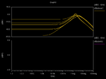
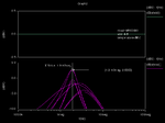
After running the ac simulation,I probed the output terminal and found that the output ac value is great than one in the frequency of unit-gain bandwidth of Error amplifier.But the trend of curve seems right.
What's the potential reasons for that. Does the PSRR great than 1 is reasonable in LDO circuit?
The simulation result is shown as attachment.(There are three variation on the simulation,including output loading, Supply voltage, temperature hence total have 8 results in the same plot)


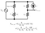
The schematic of my design also shown in here. (The bias circuit in not shown in the schematic)

Any help is really appreciated,
Thanks
I design a Low dropout voltage(LDO) regulator recently.
But I doubt that my design will work when I see the PSRR simulation result.
The simulator which I adopted is Hspice.
I set the supply voltage vdd with dc bias voltage plus ac singal (V_PSRR vdd gnd dc vdd ac=1v)
After running the ac simulation,I probed the output terminal and found that the output ac value is great than one in the frequency of unit-gain bandwidth of Error amplifier.But the trend of curve seems right.
What's the potential reasons for that. Does the PSRR great than 1 is reasonable in LDO circuit?
The simulation result is shown as attachment.(There are three variation on the simulation,including output loading, Supply voltage, temperature hence total have 8 results in the same plot)


The schematic of my design also shown in here. (The bias circuit in not shown in the schematic)

Any help is really appreciated,
Thanks


