Vermes
Advanced Member level 4

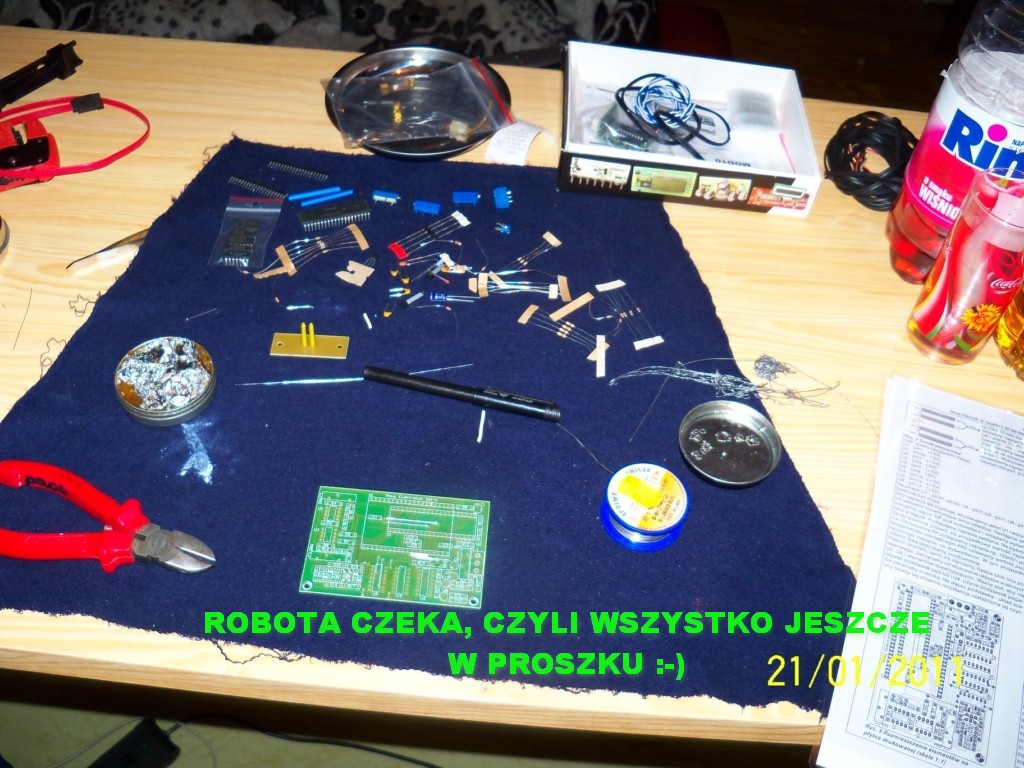
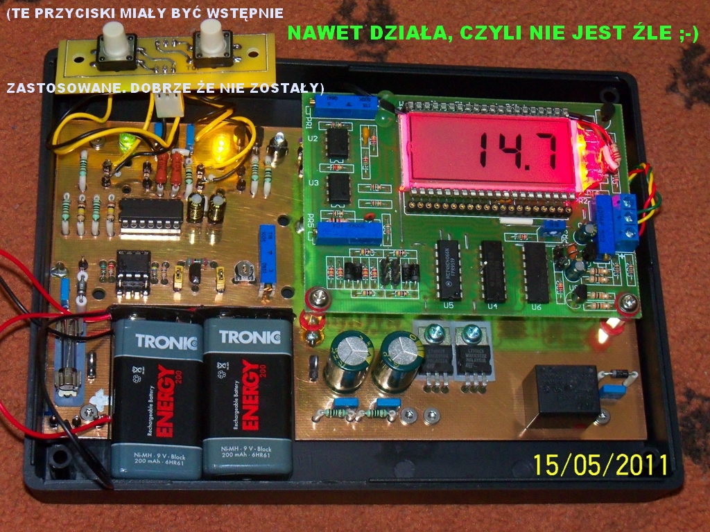
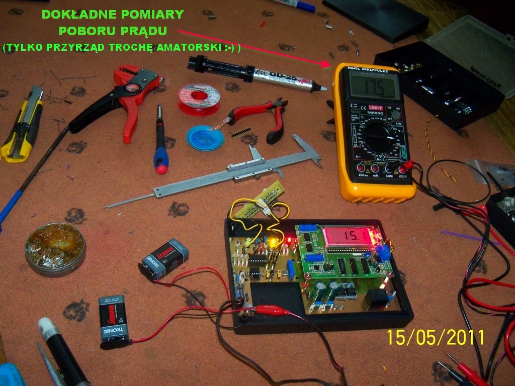
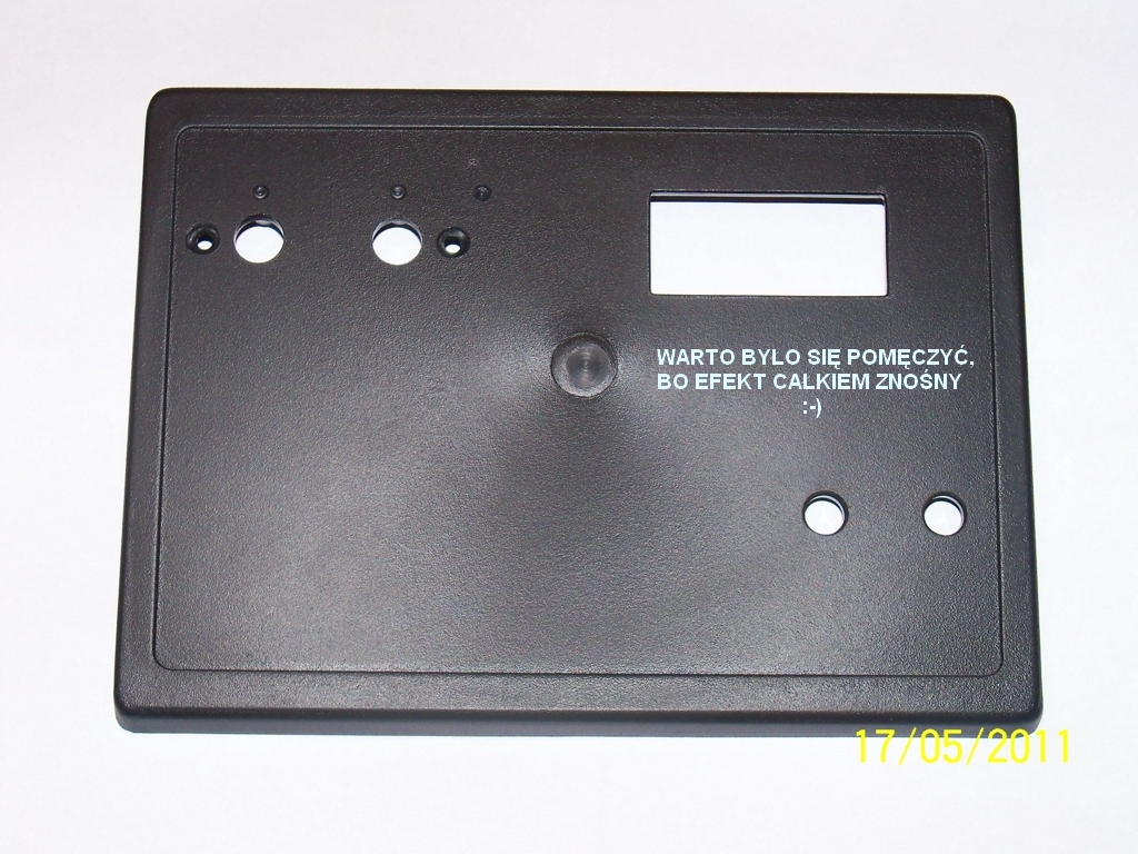
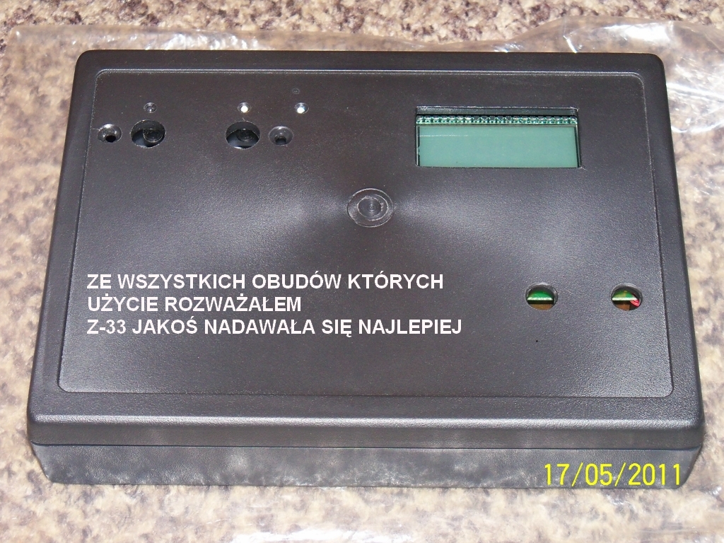
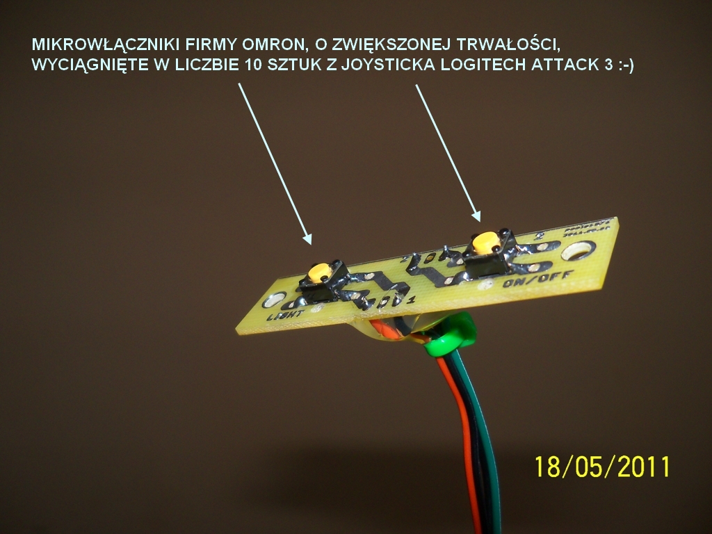
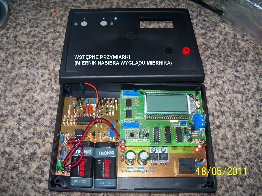
The device bases on kit NE 261-k. The housing was adapted Z-33, because its size fits the best. One of assumptions of this project was to make a meter that has backlighted display for work at low light and does not have any 'crude' mechanical switches. Also, simple battery voltage control was desired. The device uses a double switch ON/OFF on CD4013, controlled by microswitches. The current consumption for the switch in the meter is:
- state of rest (off) – 0,002mA
- the meter switched on without backlight – 42,5mA
- the meter switched on with backlight – 87mA
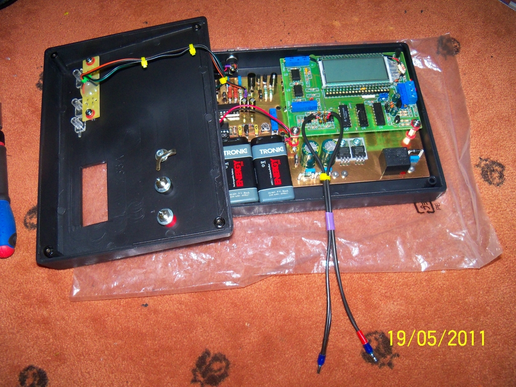
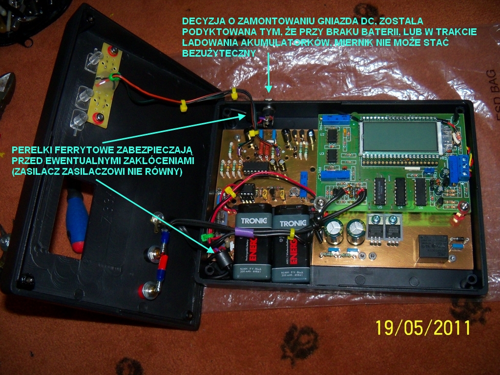
Due to the fact, that the meter requires a symmetrical +/- 7 to 8V, the use of two batteries of 9V (18V total) and the symmetrization system on stabilizers 7808 and 7908, gave desired +8, -8 on the output to power the meter. Zener diode 4V3, that powers only the system, reduced power voltage of the system CD4013 to about 16V and transistors BC337-40 switch the full voltage 18V to activate the matching transformer, meter and backlight. In addition, a simple topic fuse protection 0,4A protects the accumulators against accidental short circuit.
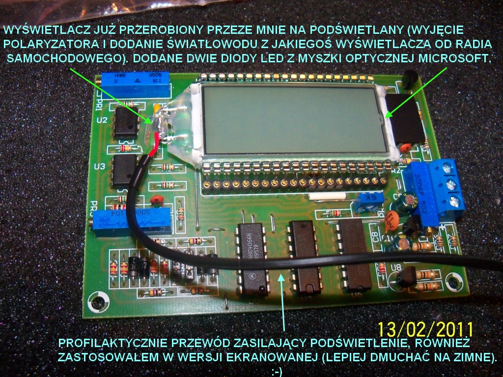
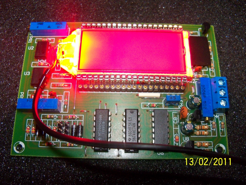
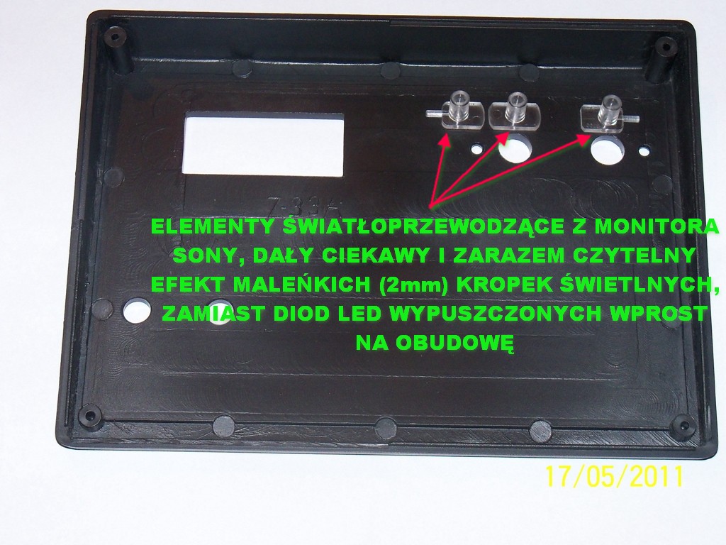
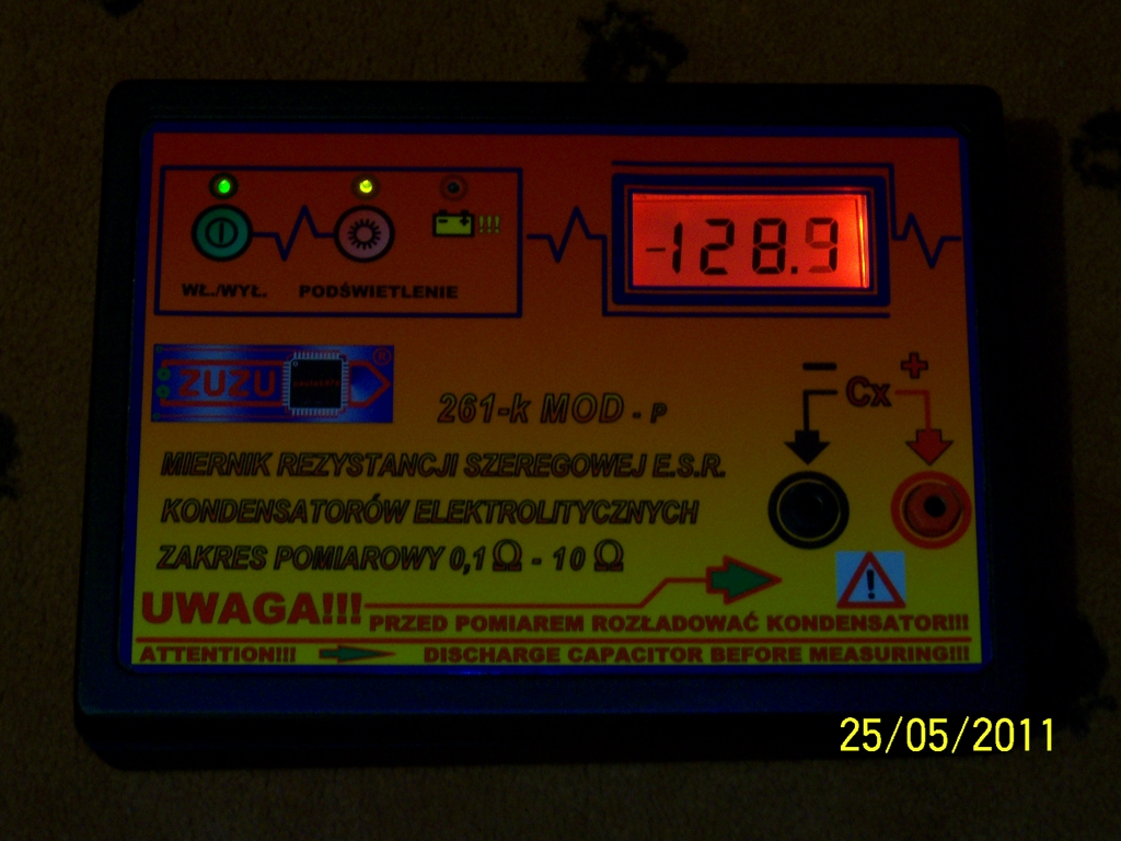
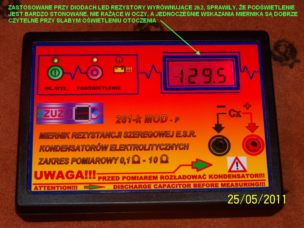
The backlight was modified one from an original meter. The polarizer was removed and a fiber bar from the car radio was inserted.
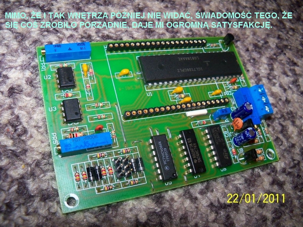
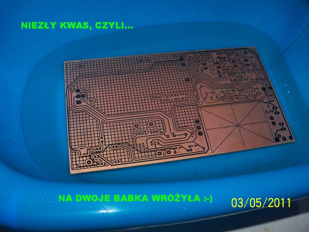
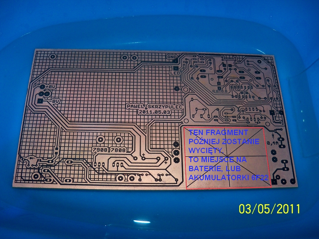
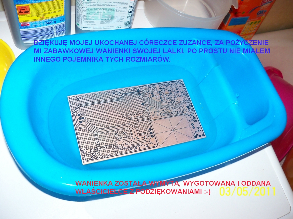
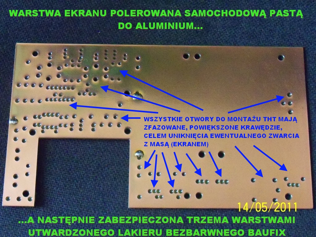
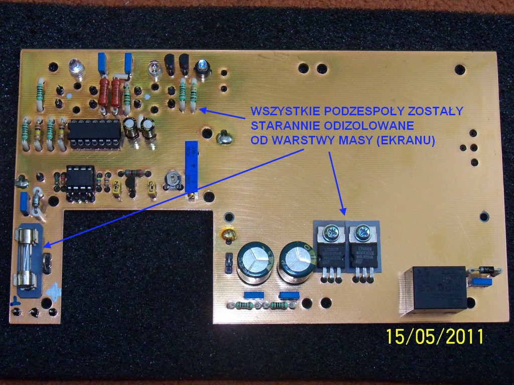
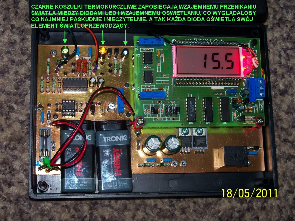
In base PCB, glass-epoxy double sided FR4 laminate was applied. The laminate is 1,5mm. From the BOTTOM side there is a suppressor screen as a grid, from the TOP side – a whole layer of copper polished and lacquered with three layers of hardened lacquer in order to protect the copper against oxidation and possible short circuit of any of the legs of THT components. The BOTTOM layer was tinned using transformer soldering iron and a large amount of flux. Each hole on the side of the screen is drilled and chamfered to avoid a possible short leg with the screen. PCB was made in iron thermal transfer method.
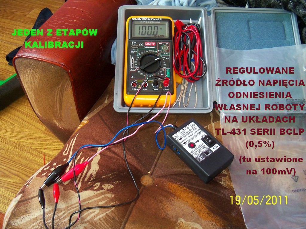
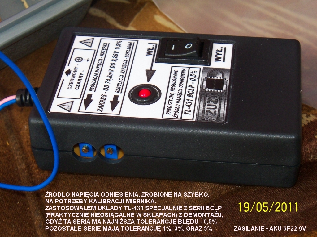
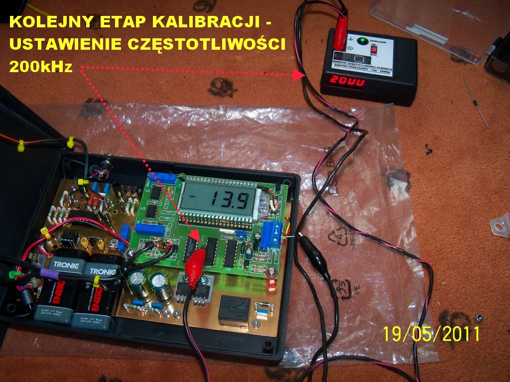
There are three stages of calibration. Firstly, voltage indications 100mV were set in the meter. Then, using a digital frequency meter, the desired frequency of 200kHz was set on the leg 11 of SN74HC74N. The next step is to reset the meter and set the indications of resistance, by measuring a reliable resistor and regulating the indications to its values. Metallized resistor 1% with a value of 3,3 ohms was used.
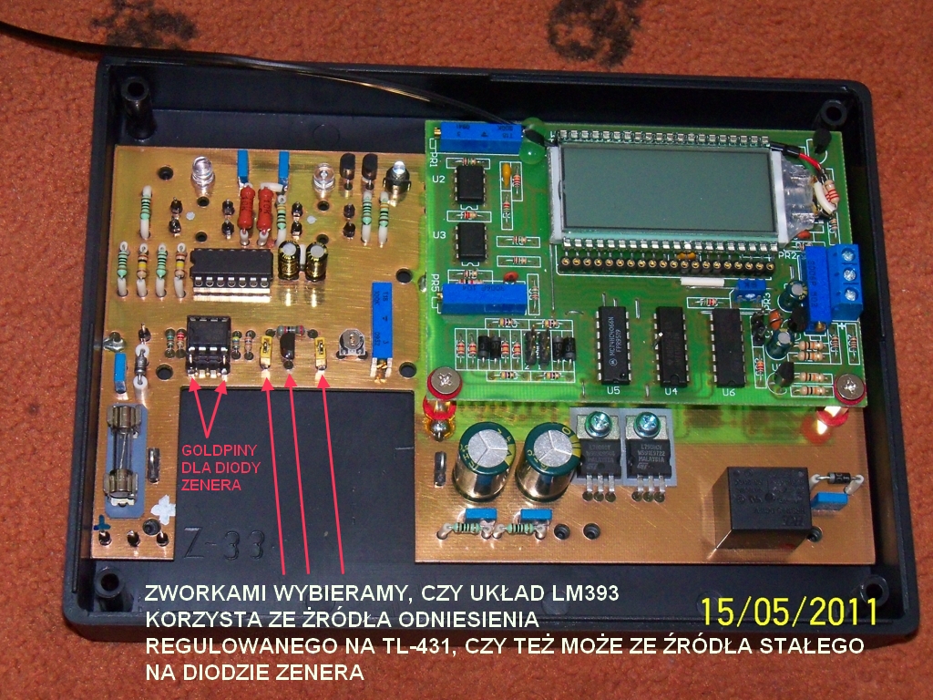
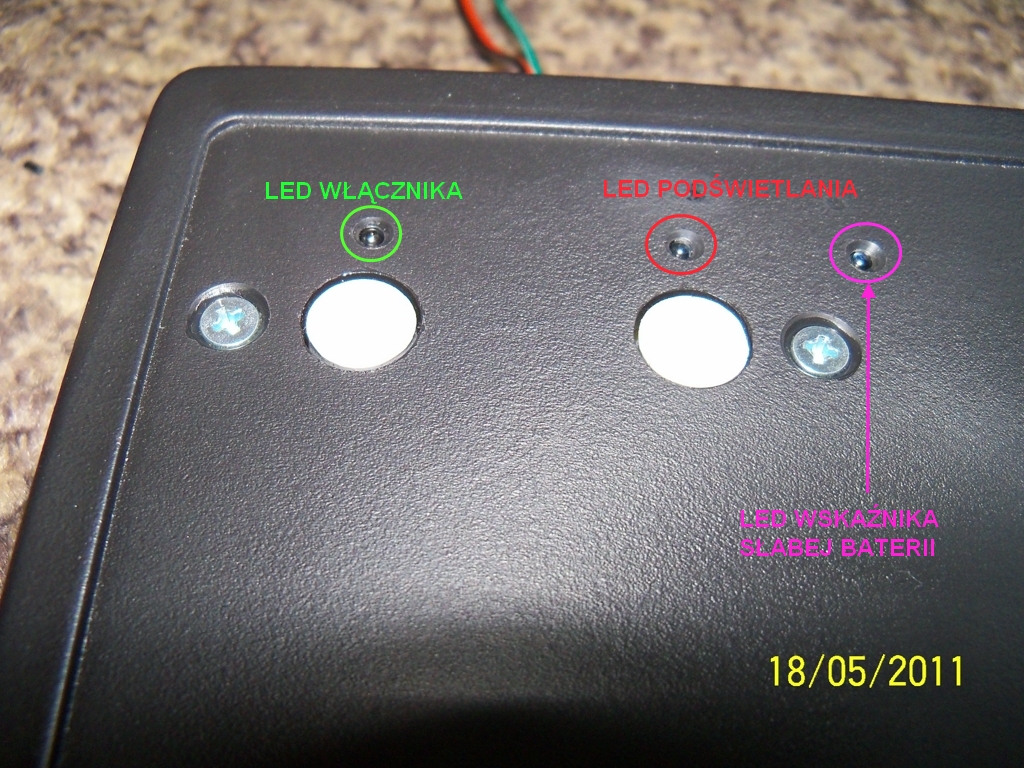
LM393 comparator controls the battery voltage. It can work in two ways set by jumpers:
- in combination with TL-431 standard and response threshold adjustable with hellitrim
- in combination with Zener diode and the response threshold rigidly dependent on the voltage of applied Zener diode
Enabling voltage of the matching transformer and thus the meter is done via the transistor BC337-40, which activates the relay 12V.
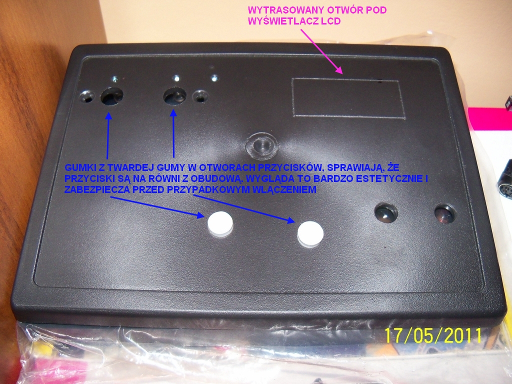
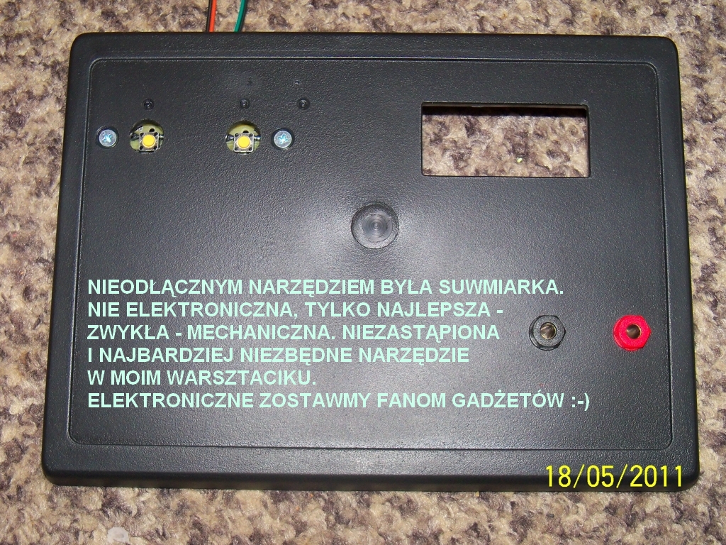
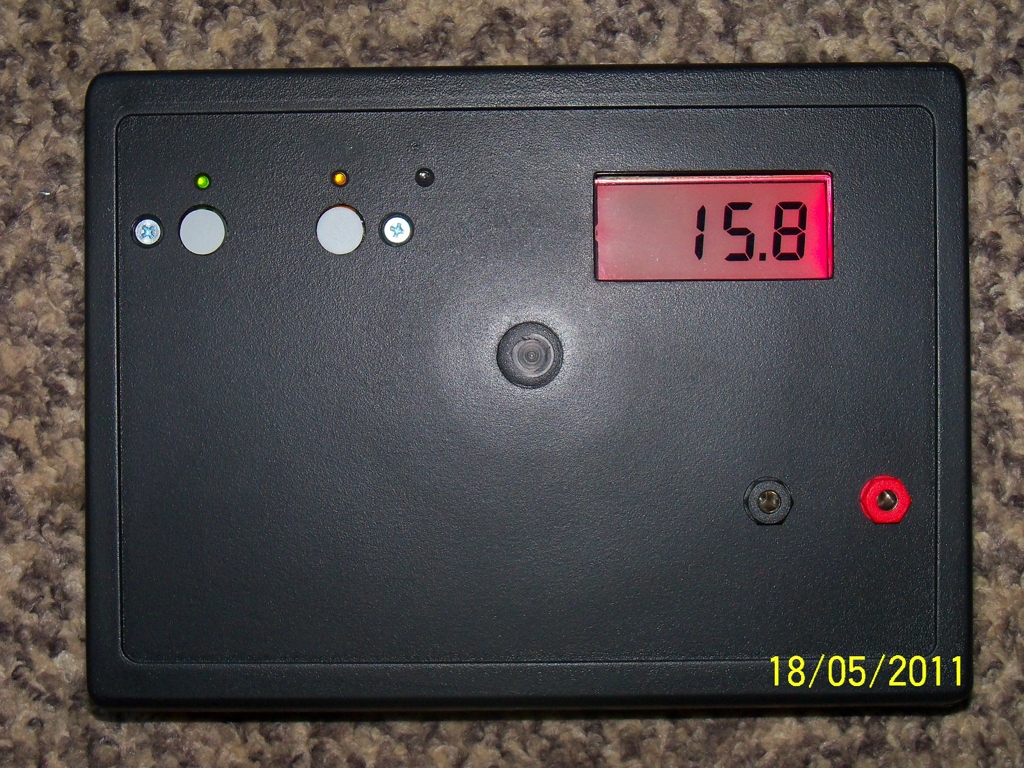
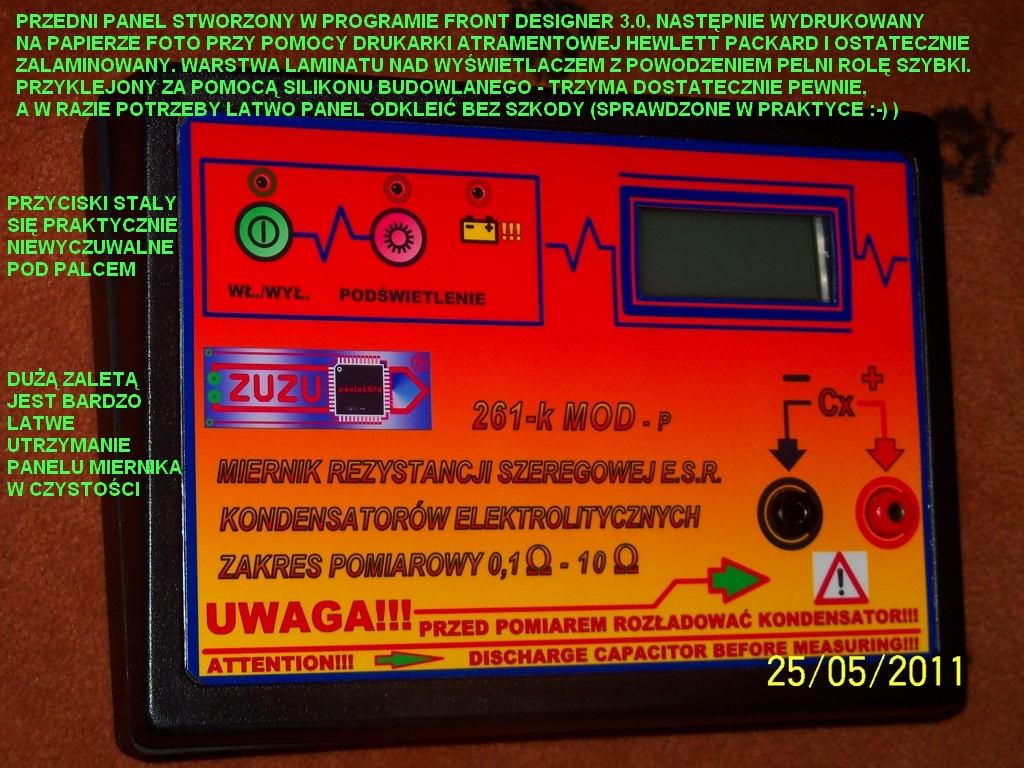
Microswitches were purposely lowered and aligned with the level of housing with rubber rollers. Sticking the panel makes the buttons invisible and undetectable under the finger and it is impossible to turn it in accidentally.
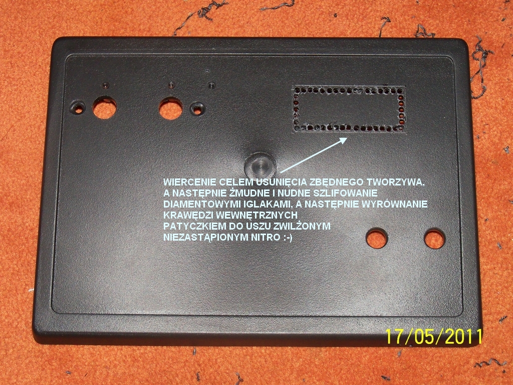
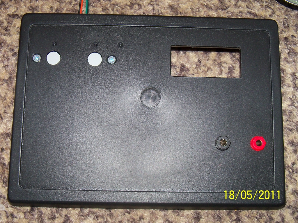
The front panel was made in Front Designer 3.0, printed on photo paper using Hewlett Packard inkjet printer, then cut a display window with a scalpel. Holes for fiber LEDs were made with steel pierces 2mm. Then the whole was laminated. The transparent, rigid after welding laminate automatically took over the function of the window protecting the display. Additionally, electrostatic protective film was put on the display.
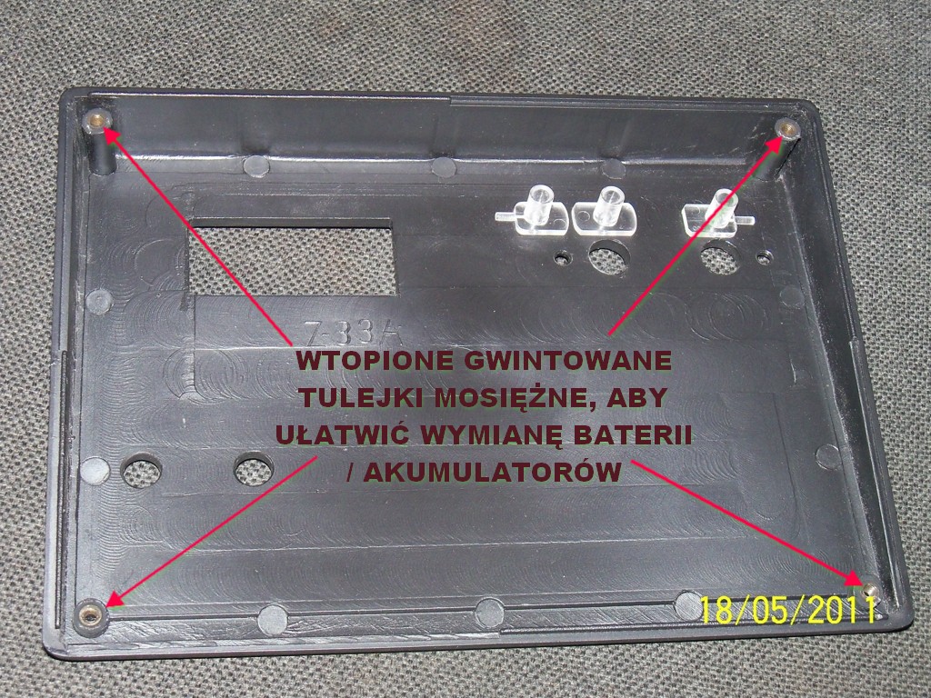
Threaded brass bushings, embedded in the assembly pins and further strengthened with glue were used in the housing. This was to protect the pins against making the thread in plastic while re-screwing the housing during changing the battery or periodic calibration.
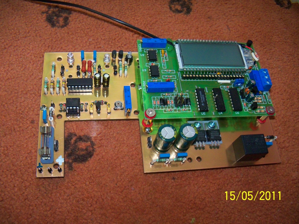
The board of the meter is placed from the bottom on the pins and the upper part is on silicon spacer tile from a motorcycle muffler.


Link to original thread (many interesting attachments) – Miernik zastępczej rezystancji szeregowej ESR kondensatorów
Last edited: