Continue to Site

Welcome to EDAboard.com

Welcome to our site! EDAboard.com is an international Electronics Discussion Forum focused on EDA software, circuits, schematics, books, theory, papers, asic, pld, 8051, DSP, Network, RF, Analog Design, PCB, Service Manuals... and a whole lot more! To participate you need to register. Registration is free. Click here to register now.

The input given to Piezo Speaker is an analogue signal or digital signal?

Status
Not open for further replies.

Jay Foonglw

Newbie level 2
Joined
Feb 16, 2015
Messages
2
Helped
0
Reputation
0
Reaction score
0
Trophy points
1
Activity points
19
Hello, I want to ask the input given to this Piezo speaker is an analogue signal or digital signal? This is because I am using digital output pin of Arduino Uno board to connect this speaker, is that okay?

Besides, if this speaker require an input analogue signal, then should I use Digital to Analogue Converter where convert the digital output pin of Arduino into analogue signal first and then feed to speaker?

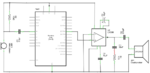
The diagram of the connection between Arduino and speaker is shown in this attachment.

Thanks for helping.
 

Attachments

  • Circuit Diagram for Hardware.PNG
    Circuit Diagram for Hardware.PNG
    55.4 KB · Views: 105

It depends on the target application of the circuit.

If the main purpose is to act just as an alarm system based on sound detection or something similar, would work as it is. However if the uC perform some signal processing inside, like a digital filtering, I presume that the presence of the capacitor without a biasing circuit at the uC side would clamp the waveform.
 

All speakers are analog but the signal can be created with DAC or PWM (Class D)

For PWM the clock rate must be at least 10x the signal max frequency and is usually filtered out.

Otherwise a piezo alarm just uses an amplified clock.
 

A piezo speaker might be a pretty big tweeter to make high frequency sounds loudly, or it might be a little squeaky thing used in a greeting card. It would rarely be used with a microphone.

You show a circuit that uses an LM386 power amplifier and an 8 ohm real speaker. The amplifier has a gain of 200 times. The output peaks of the Arduino is 5V then the output of the amplifier will try to go to 5V x 200= 1000V but with a 5V supply the maximum output from the LM386 is only about 4V so the output will be severely distorted.

A piezo speaker uses a very low amount of current so it can be directly connected to the output of the Arduino without the amplifier.
 

Dear Audioguru,

Ya. I am using 8 ohm with 0.25 Watt Speaker. But If I am not using amplifier, then output sound from the speaker will be small which is not easy to be listened.

Since you said the output will be distorted if I am using this configuration. Then, can you suggest me how to overcome this problem?

Thanks for helping.

Regards,
Jay
 

In your first post you said the speaker is piezo, not 8 ohms. A piezo speaker has a very high impedance so it can be driven directly from the Arduino. An 8 ohm speaker has a very low impedance so it needs a power amplifier to provide it with enough current.
Since the output of the LM386 amplifier causes distortion when its gain is too high and/or when its input signal level is too high then simply read its datasheet.

The datasheet for the LM386 amplifier shows that the input should use a series capacitor to block DC. It also shows that the capacitor between pin 1 and pin 8 increases the gain 10 times to 200 times. Remove it, then the gain is 20 times. The maximum undistorted output into an 8 ohm speaker when the supply is only 5V is shown on a graph on the datasheet to be about 3V peak to peak. Since the gain is 20 then the maximum input without distortion is 3V/20= 0.15Vp-p.

The output of the Arduino is about 5V p-p so make an attenuator with two resistors between the Arduino and the input of the LM386 input. The series capacitor should feed the input of the attenuator.

But the output of the Arduino is not analog, it is digital rectangular waves unless you are trying to make PWM class-D audio. The PWM signal has a high carrier frequency that should be filtered out in the attenuator so that the LM386 does not try to feed it to the speaker which might cause it to get hot.

The 250uf value of the capacitor feeding the speaker will cut low frequencies below 80Hz.
 

Status
Not open for further replies.

Part and Inventory Search

Welcome to EDABoard.com

Sponsor

Back
Top