Continue to Site

Welcome to EDAboard.com

Welcome to our site! EDAboard.com is an international Electronics Discussion Forum focused on EDA software, circuits, schematics, books, theory, papers, asic, pld, 8051, DSP, Network, RF, Analog Design, PCB, Service Manuals... and a whole lot more! To participate you need to register. Registration is free. Click here to register now.

The curvature of my BGR output is wrong. Why?

Status
Not open for further replies.

palmeiras

Full Member level 6
Joined
Feb 22, 2010
Messages
375
Helped
61
Reputation
122
Reaction score
50
Trophy points
1,308
Location
South America
Activity points
4,199
Hi everybody

I have designed one traditional BGR as shown in figure 1.
And I didn’t achieve the corrected and expected curvature of the output voltage, when I used vertical parasitic PNP2 (emitter area =2x2). The output generated by this reference is shown in figure 3. As one can see, at high temperatures, the output voltage increases a lot. There is no value for the aspect ratio of the resistors that overcames this effect.

However, when I used PNP10 (emitter area = 10x10), the output voltage, generated by this SAME reference, is corrected. It is shown in figure 2. It doesn’t increases at high temperature.

Why??? Why isn’t it possible to achieve the corrected curvature with PNP2?

The values of BETA for both devices (PNP2, PNP10) are similar:

BETA_PNP2 @27=2,614
BETA_PNP10 @27=2,633

BETA_PNP2 @120=4,072
BETA_PNP10@120=3,869

Obs: I used an ideal op-amp (described in verilog-ams) in this design.

Thanks!
 

I am not near my computer at the moment but I have seen that effect before and would suspect high temperature leakage. By the way, are those betas really 2600 or 2.6? (continental decimal)

Keith

Added after 1 hours:

By the way, the reason I think it is leakage not beta is because I saw that shape on an SOI bandgap at 250C and I used diodes not transistors.

Keith
 

    palmeiras

    Points: 2
    Helpful Answer Positive Rating
I think your ctat component is more inherently. What correction are you trying to do ? is it second order?


Amarnath
 

Curvature correction tries to correct the second order
(parabolic) curve with a third order (cubic) term. From
the look of things, maybe you are just over-correcting
(the second curve,sure looks cubic).

Of course a lot of the effects you are trying to fix, stem
from behaviors that often receive little attention in model
development (it's "just" a substrate PNP, who would use
that?). If your silicon and simulations don't agree, and you
expect to be doing more with the foundry, you might be
wanting to determine where the discrepancies lie.
 

How much current are you putting through the BJT's. You do not want too much current in your bandgap. People like to have the BJT's operate at the exponential current based on Ic Vs Vbe curve
 

Hi guys!

Thanks very much for your attention. However, this effect is not clear for me, yet.

(a) Keith,
If the rising of output voltage is result of leakage, why doesn’t this effect appear in both cases? Why does they have different behaviour?

(b) Amarnath,
I want to design the BGR (illustrated in the figure) using PNP2. What do I have to do in order to avoid the increasing of VREF at high temperatures? That is, to get the expected output curvature?

(c) Dick_freebird,
I agree with you… but I am not using any correction curvature technique. It looks like, but it is not. So, what is reason of this increasing at high temp.?¸

Thanks again,

Palmeiras

Added after 2 minutes:

Hi rajesh_a03,

The current in each branch is 5uA...

Thanks,
 

Is M1&M2 still delivering the same amont of current at high temp?
 

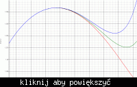
While it isn't a guarantee that your problem is caused by leakage, I have attached a graph showing the effect of transistor leakage. The design is the same as yours but without M1/M2 with a 1:4 transistor ratio and the red trace being normal. I then took a reverse biased diode & used current controlled current sources to add some leakage across the transistors. The effect, depending on the amount of leakage added, is shown in the other traces.

As I mentioned earlier, I have seen the same effect on an SOI bandgap where I used diodes rather than transistors, although it didn't occur until 250C.

Keith.


    palmeiras

    Points: 2
    Helpful Answer Positive Rating
tdy said:
Is M1&M2 still delivering the same amont of current at high temp?

Yes! M1 and M2 are operating in saturation region and continue to supply the designed current at high temperature.

Regards,

Palmeiras

Added after 2 hours 13 minutes:

Keith,

It is a good hypothesis about what it is happening. I tried to verify the BJT parameters, in order to identify if the leakage current of PNP2 transistor is higher than PNP5 transistor. However, I didn't find any relevant information. I verified some SPICE parameters (NE, NC, ISE, ISC, NR, ... ) and they seem to be almost similar. Although, a fast view in these parameters can not say many things about it. I will think a little more about this.

I would like to simulate this leakage effect ( as you did), to verify the impact on VREF.
If possible, could you send to me a snapshot of your circuit? (by e-mail or post here).

Thank you very much,

Palmeiras
 

Status
Not open for further replies.

Part and Inventory Search

Welcome to EDABoard.com

Sponsor

Back
Top