Pavel1986STula
Newbie level 6
- Joined
- Sep 21, 2010
- Messages
- 11
- Helped
- 0
- Reputation
- 0
- Reaction score
- 0
- Trophy points
- 1,281
- Location
- Russia, Tula
- Activity points
- 1,403
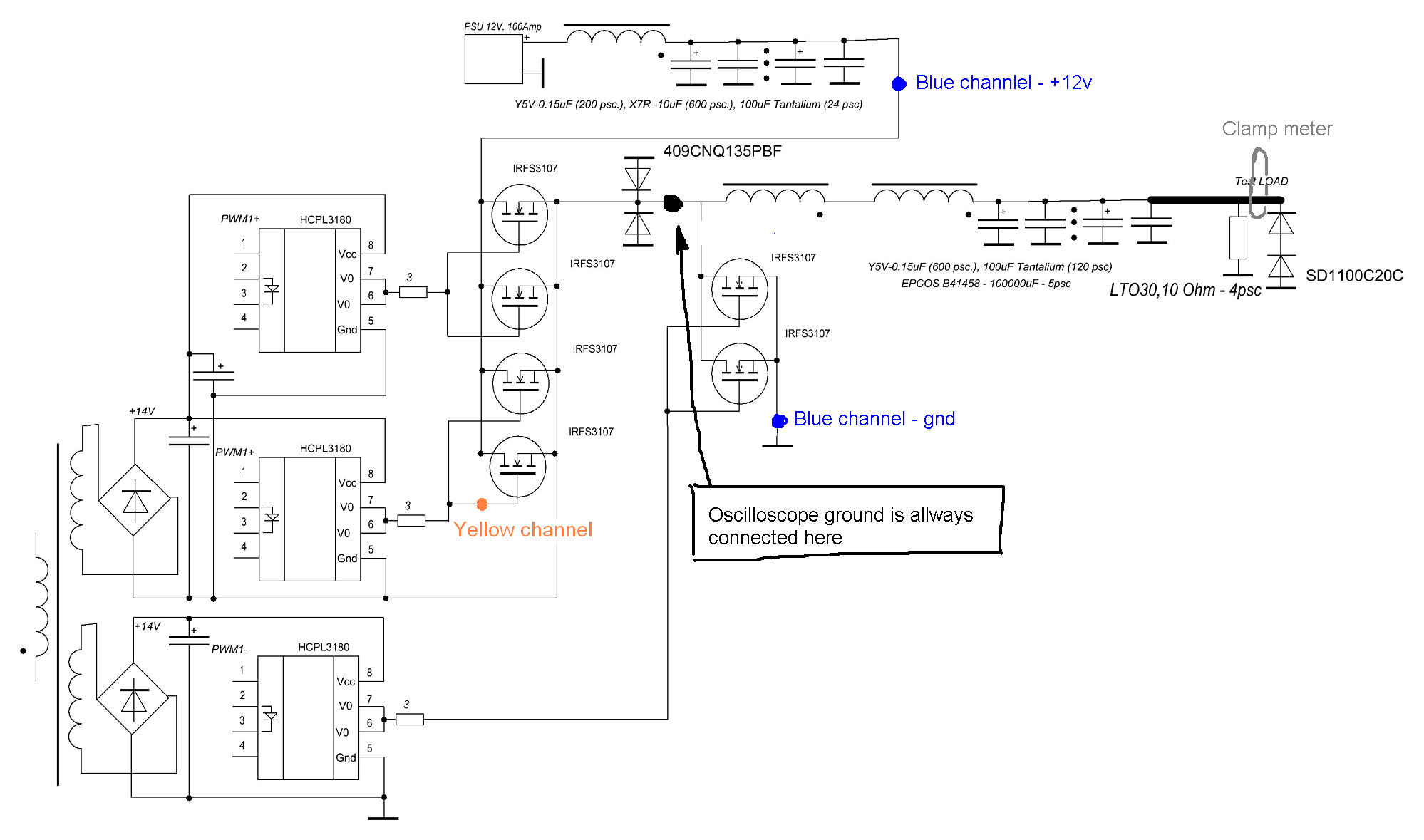
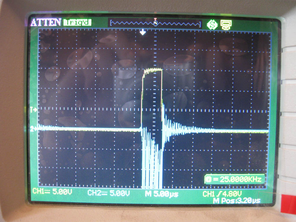
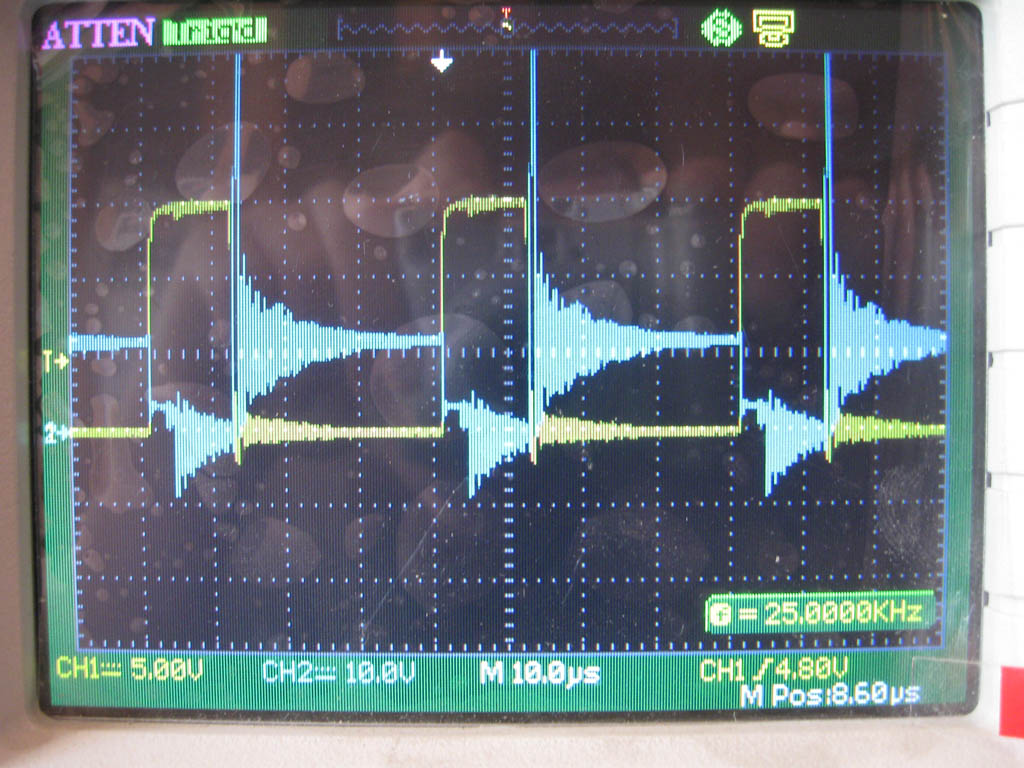
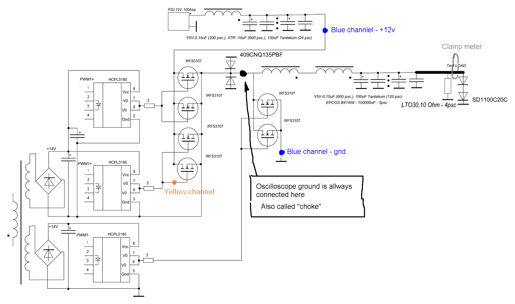
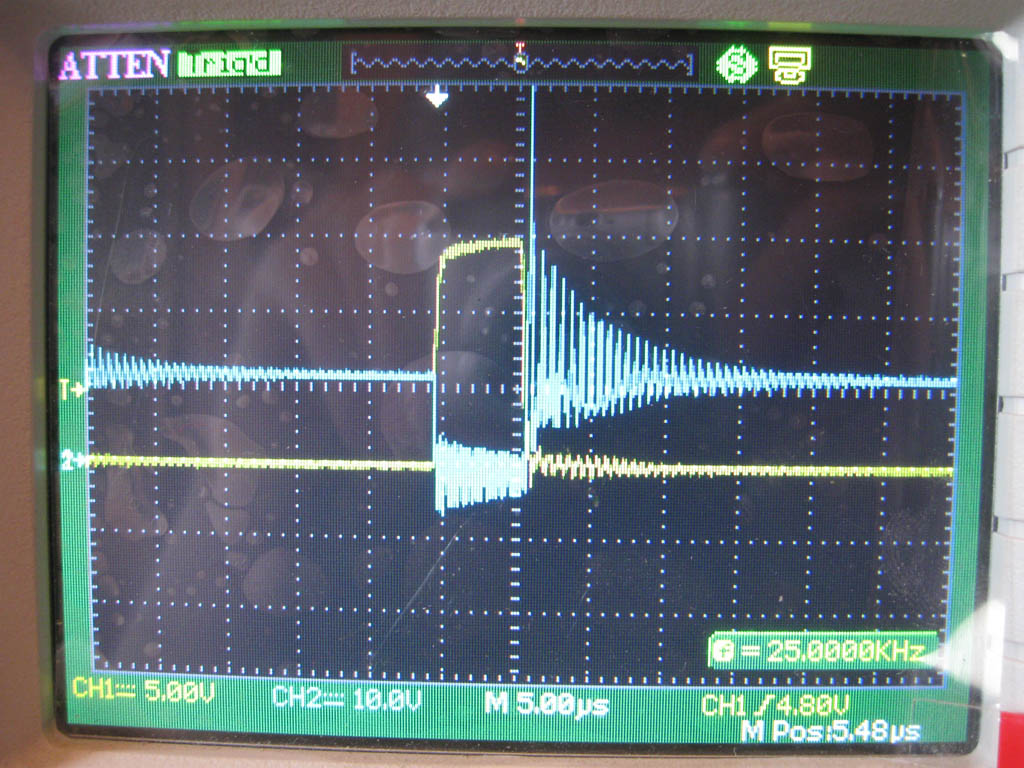
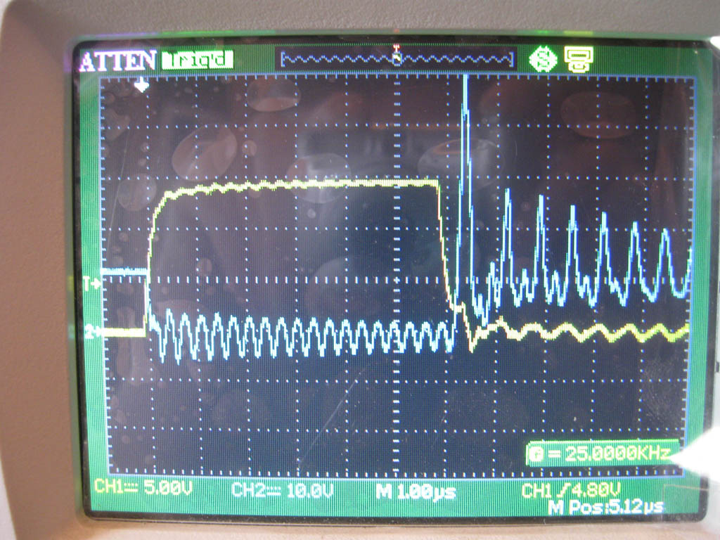
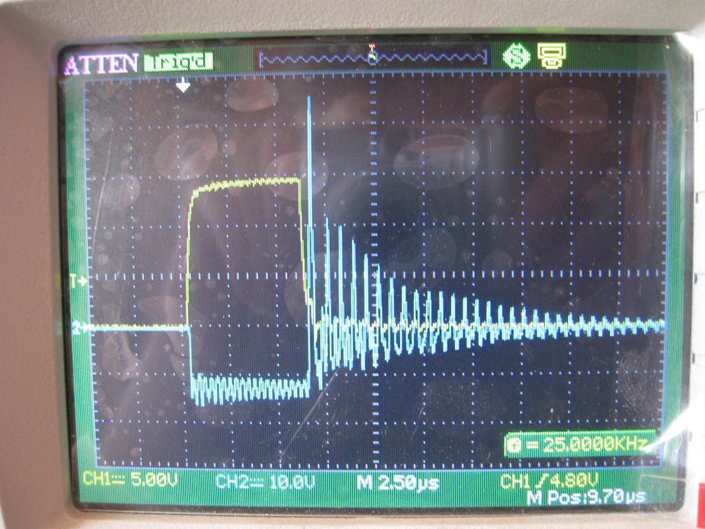
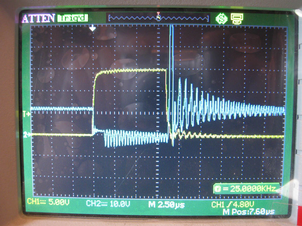
Hello. I build high power DC-DC PSU with digital PWM control. I want to get 150 Amps from 1 phase. Something does not work right – efficiency is 50%, mosfets heat much.
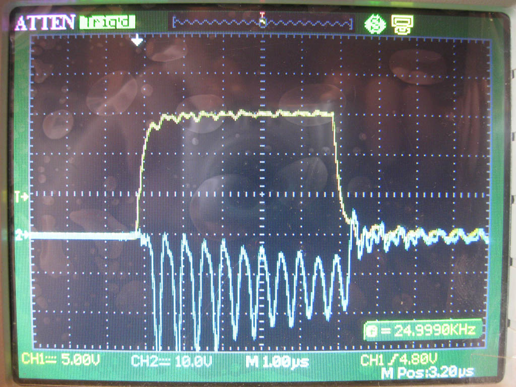
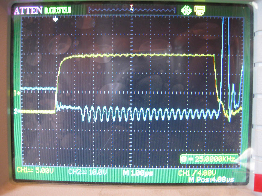
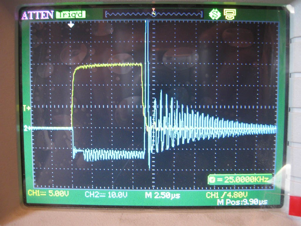
Frequency is 25khz; duty cycle on 1.76v 100amps load - 29.2%; 12v power supply current – 27.3 amps.
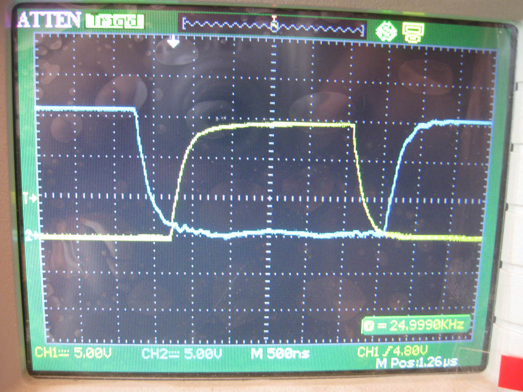
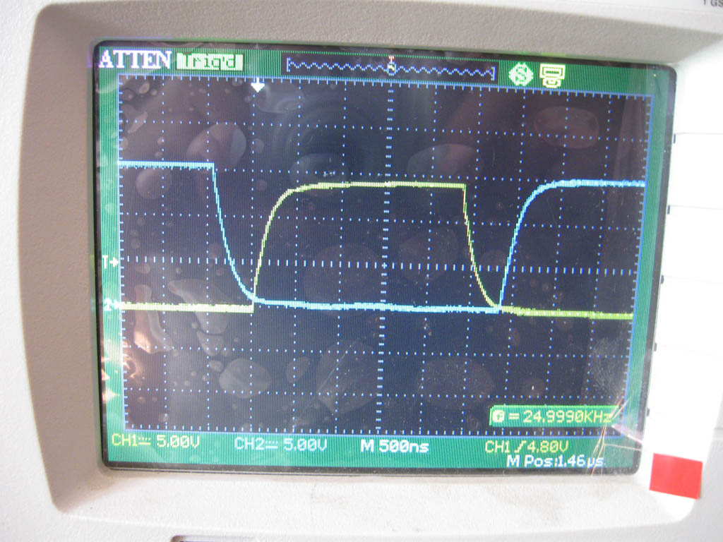
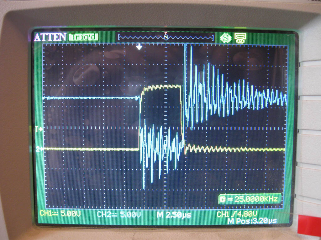
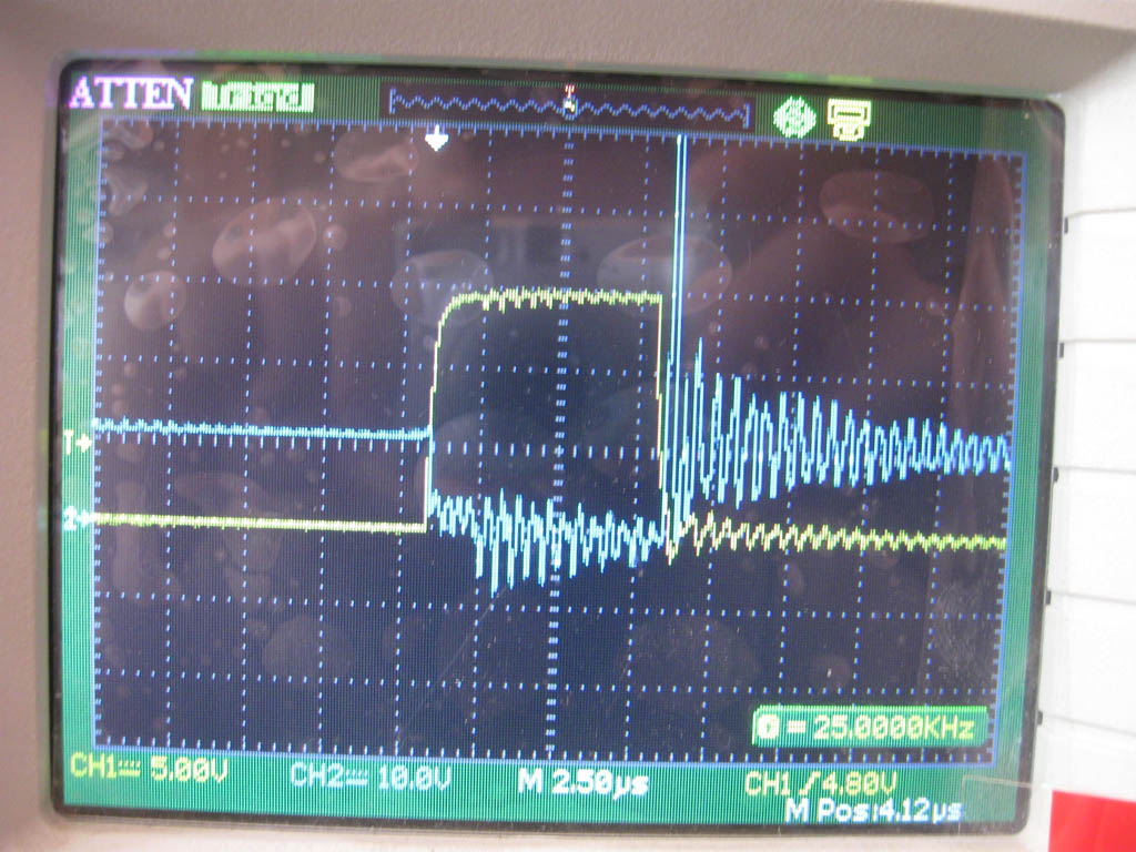
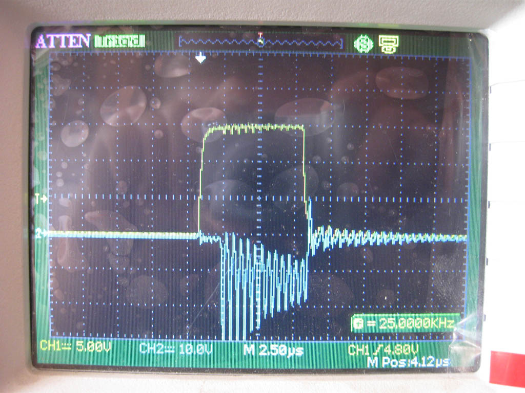
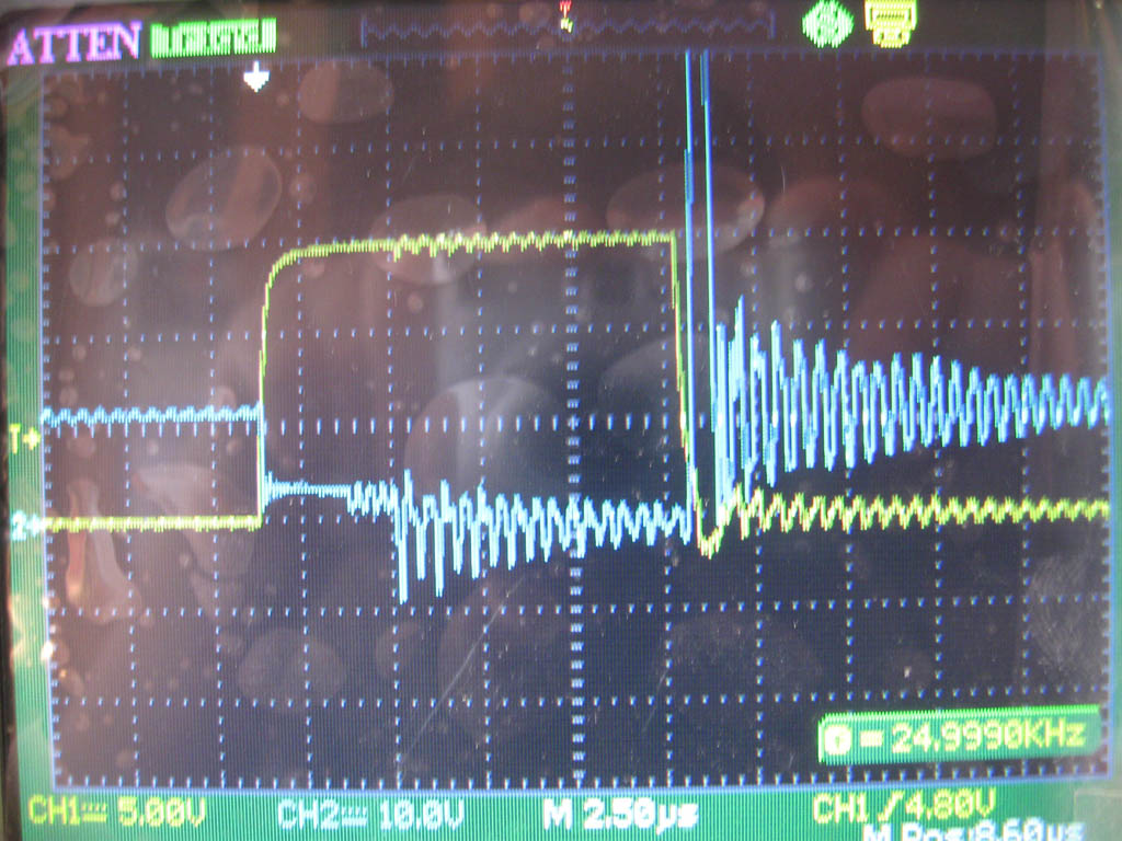
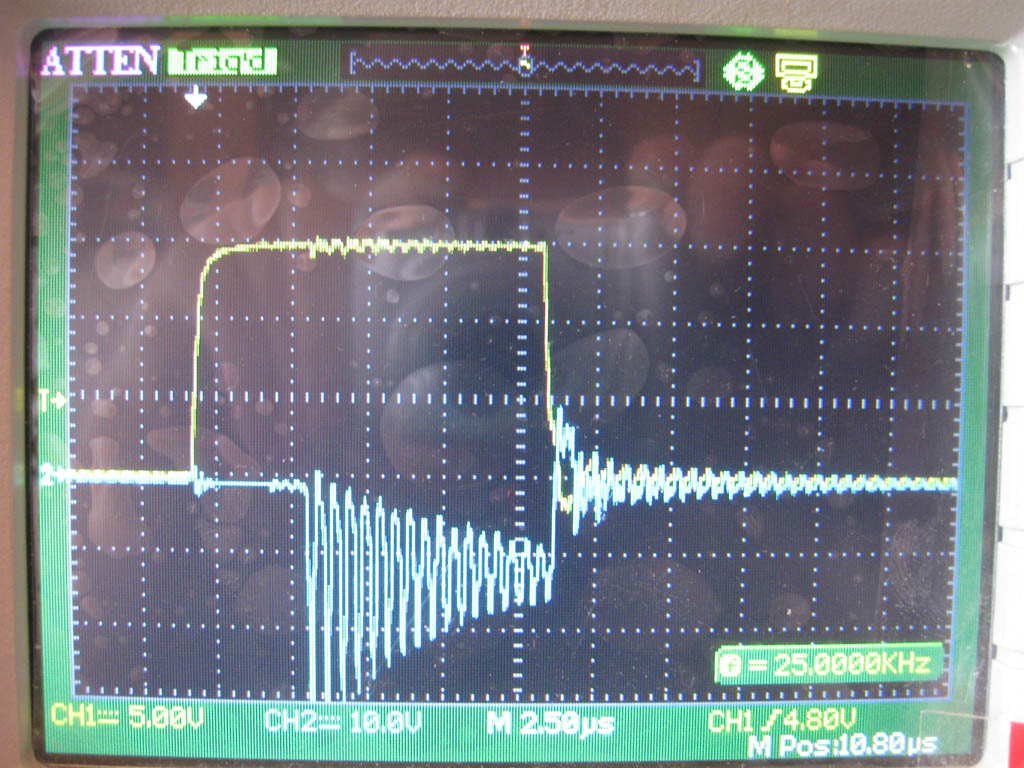
I post schematic with oscilloscope measure points. The second picture is gate-source voltage only. Reverse mosfets work well (100% no through current, they are cold with no cooling) but current divides in half between them and diode(DC current measured with clamp meter).
The choke has handmade frame for 4 E80 ferrites. There is 7.5 turns of double copper 0.5mm x 55mm tape. I don’t know real inductance of the choke – tests were with three series. Any results do not differ much with two chokes. Ferrites are on one side only. When tested tape was warm, ferrites – cold.
Please help me to understand what is wrong?!!


Frequency is 25khz; duty cycle on 1.76v 100amps load - 29.2%; 12v power supply current – 27.3 amps.
I post schematic with oscilloscope measure points. The second picture is gate-source voltage only. Reverse mosfets work well (100% no through current, they are cold with no cooling) but current divides in half between them and diode(DC current measured with clamp meter).
The choke has handmade frame for 4 E80 ferrites. There is 7.5 turns of double copper 0.5mm x 55mm tape. I don’t know real inductance of the choke – tests were with three series. Any results do not differ much with two chokes. Ferrites are on one side only. When tested tape was warm, ferrites – cold.
Please help me to understand what is wrong?!!
Last edited: