Continue to Site

Welcome to EDAboard.com

Welcome to our site! EDAboard.com is an international Electronics Discussion Forum focused on EDA software, circuits, schematics, books, theory, papers, asic, pld, 8051, DSP, Network, RF, Analog Design, PCB, Service Manuals... and a whole lot more! To participate you need to register. Registration is free. Click here to register now.

[51] the circuit does not be in stable

Status
Not open for further replies.

chasekan@gmail.com

Member level 1
Joined
Jun 23, 2013
Messages
35
Helped
1
Reputation
2
Reaction score
1
Trophy points
8
Activity points
255
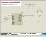
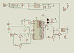
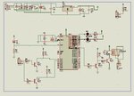
hi, herewith i ve attached a circuit, function of this circuit is water level controller in the water tank.
herewith i ve attached the schematic,here the problem is, the controller does not stable some time and the controller does not work as per the program and some other time it does work as per the program,what could be the reason,but it works well in proteus,thanks in advance
Code:
                INPUT1 EQU P1.0
		INPUT2 EQU P1.1
		GREEN EQU P0.0
		RED EQU P0.1
		RELAY EQU P2.0
		ORG 00H
STOP:	        CLR RED
		SETB GREEN
		SETB RELAY
L1:		JNB INPUT2,L1
L2:		JNB INPUT1,L2
		SETB RED
		CLR GREEN
		CLR RELAY
L3:		JB INPUT1,L3
L4:		JB INPUT2,L4
		SETB RELAY
		CLR RED
		SETB GREEN
		SJMP STOP
		END
 

Attachments

  • untitled.JPG
    untitled.JPG
    38 KB · Views: 86
Last edited by a moderator:

Hi,

I don't use that chip but some suggestions.

You do not say what the level sensor is, optical, float switch ??

Either way you are doing a read of the sensor then acting on it and going around the loop again in a few micro seconds.
You want to add a Delay between readings and when you do read an input, perform a debounce routine with a little delay between each read to ensure is a positive read.
example
Read1
if on
delay a little ,50ms
still on - yes
act
done
delay 250ms before
loop

Regarding your diagram, most small relays only need a single transistor to drive them on, wonder why you are using 2 ?

Also with no details of your input sensors, again bit surprised to see the transistors on the inputs ?
 

thanks for your reply,your technique is very useful along with that i ve used 100nf capacitor as a filter now it works fine, I am not much familiar with PNP transistor calculation and manipulation, thats why i ve used two NPN transistor in the relay as an inverter switch, it ll switch on the relay when binary "0" is sent by the controller,i ve used a driver circuit in the input side because i am not using optical or float controller because it costs little more, ought to avoid the cost i ve supplied 5v supply to the water(this circuit is for water level controller) when the supply voltage detected at the input the transistor will drive the appropriate pin to binary"0".

- - - Updated - - -

hi for the above circuit diagram 7805 gets heated much more,can anybody tell me how to troubleshoot
 

Hi,

Its difficult to see your design clearly, try saving your design and Send To ..Zip so your can attach the file here.

Have shown how you can connect a relay via a single npn transistor, so a 1 to the port will turn it on, which is logically better than 0.
It also shows the correct way to wire the Reset pin, you seem to have the R and C the wrong way round.

Not quiet sure what you mean you are using for the water sensor, sounds like you are saying to are putting +5v directly into the water ??
What is the receiver, another pics of wire ?
Probably a little float switch is a much better way, they are so cheap its not worth messing with other cruder methods.

As for the 7805 getting hot, do you mean if you place the metal tab between two fingers it gets too hot to hold in how many seconds?

Basically with a proper circuit is should only get slightly warm though its always good practice to fit a small heatsink .

Think you need to check for short circuits along with getting you circuit correct.
As well as a .dsn of you full circuit, a photo of your board can also help locate a problem.
 

Attachments

  • 000087.jpg
    000087.jpg
    81.8 KB · Views: 69
  • 000088.jpg
    000088.jpg
    19.3 KB · Views: 69

hi,now i ve scrutinized my circuit, you can watch in my circuit that i ve used 5v supply for relay from 7805, as relay drawn more current it got heated much more.now i ve drawn it next after 1000uf (c1)capacitor now it works fine.8051 functions with active high reset(in working condition it should be kept low) but your is extremely reverse (active low), so your circuit is correct for your controller mine is correct for my controller but i dont know why you ve used a diode parallel to the resistor r1, 8051 will set all pin high immediately when switched on the controller before executing the program so ought to avoid a small spike current for the relay every time switching on the circuit i ve designed an inverter circuit.in my circuit j3 is the tX (wire will taken and put in to the bottom of water tank), j2 is the receiver(wire will be put in to the water in appropriate place for example middle and top)

- - - Updated - - -

hi can you explain me, how to change the beta value of transistor in proteus
 

Hi,

The diode in the reset circiut is not essential, it helps discharge the capacitor quickly when Vdd is removed,

No idea if you can change a transistors beta value in proteus, though wonder , for your circiut, why you would want to do that.
With the correct transistor and base resistor you should not have a problem.

However, that said, driving a 5v relay on the same power line as the pic is never the best way.

Any interference on Vdd from the switching of the coil or contacts goes straight to the pic.

Also a 5v relay driven though a transistor will be Vdd - 0.6v so its getting close to the relays lower operating voltage.

You say the regulator is still getting hot, what are the voltage/current/resistance values of the relays coil ?
Also its difficult to see from your diagram how you are sending/returning 5v into the water.

Its generally simpler to use a 12v relay with the power from the input to the 7805 so reducing line voltage interference.
 

hi i ve attached the circuit herewith,
now i ve an another problem, there you can see a relay in my circuit, that relay drives an another relay of 230v operating coil and 230v, 24amp switching supply, when i add up that relay with this circuit sometime the controller does not function well, what could be reason how to avoid that.
 

Attachments

  • untitled.JPG
    untitled.JPG
    371.7 KB · Views: 68

Hi,

Like I was talking about in the previous post, a switching relay will cause interference, a big relay switching 24amps ( voltage / dc or ac ?) will create even more.

Your circuit board design, housing and designed in filters and suppressor will all help protect against such noise.

Also your program code must be designed with consideration to the possibility of noise, things like watchdogs etc.

There is no easy single answer as every project and relay load is different.

Suggest you start by using some suitable relay Contact suppressors , the type must be proper mains rated devices eg Class X or Y if mains is being switched , possibly different if dc is being switched.

Here is a good starting place https://www3.panasonic.biz/ac/ae/control/relay/cautions_use/index.jsp
 

Zip and post your code and Proteus file. Your relay circuit is not good. Initially when circuit is powered, before MCU turns ON Q4 turns on and relay turns ON and then MCU will make relay to turn OFF. To avoid this you have to use one transistor to drive the relay.

Edit: Use the NPN circuit I have attached. Make clear 2.0 initially and set 2.0 when water level is low.
 

Attachments

  • relay.rar
    13.7 KB · Views: 55

hi herewith i ve attached zip file

- - - Updated - - -

hi thanks for your support, can you explain how to calculate the resister values in your PNP transistor circuit, especially r1 and r2
thanks
 

Attachments

  • New Folder (3).rar
    22.1 KB · Views: 53

hi your circuit works fine in simulation, but you must use a emitter resister(for npn transistor but no idea about PNP), because transistor is temperature dependent, if you dont use that, in some occasion the relay will get stuck so as the transistor.

- - - Updated - - -

hi does anyone know calculation using PNP transistor, show me the related article, thanks
 

“Selfishness is not living as one wishes to live, it is asking others to live as one wishes to live.”
― Oscar Wilde
 

Hi,

We have tried our best to help you but cannot seem to get our points across to you clearly.

I have not used that micro or used its assembly code but the things you are saying just do not seem right.

You say to have to use a logic 0 to turn the relay on because when the chip boots it turns the relay on for a split second.
That mean the ports are initalised as Outputs and set High, thats just the worst possible condition for any chip.
Can you show me anything in the chips datasheet to confirm this.

I would strongly suspect that your program coding is not correct and is doing that as a result of some code error.

Even if it was true that it boots high, you could easily add a small capacitor to the transistor circuit so simply absorb any short spike at power on, so allowing normal output logic to be used.

Regarding the output transistors, we have both provided details of transistor / relay drivers used in industry for years, they work.

You keep saying the transistors are temperature dependent and need emitter resistors; certainly not for simple relay drivers like these.

If your actual circuit transistors are getting hot you must have a short / build error or your relay is an unsuitable type, if you can give full details of its parameters, maker and part number we can check that for you.

We are all here to help, but meet us half way.....
 

What is the resistance of your relay coil? How much current flows through relay coil and transistor collector-emitter? I guess current will not be more than 150 mA . BC547 and BC557 's max collector current is 500 mA. Your relay coil current will be less than 30% of max collector current. You don't have to worry about it.

I doubt that relay or transistor is hanging. Maybe your MCU is hanging as there is no isolation between MCU and relay circuit. Use a opto-isolator between MCU and transistor.
 

Attachments

  • relay.rar
    20.5 KB · Views: 49

hi friends,i ve solved all the problem in circuit now it works fine,
my question is finding the values in PNP transistor by calculation..
the below circuit is uploaded by my friend "wb 100" in this forum,
in that circuit he used a pnp transistor, i want to know the calculating procedure.that how to find resistor value of PNP,
by short of time can upload quality material, there are lot article for NPN transistor but only few for PNP transistor.
thanks lot friends
 

Attachments

  • relay (2).rar
    13.7 KB · Views: 55

hi the above relay driver does not pull down the 8051 controller pin in proteus simulation.
 

Status
Not open for further replies.

Similar threads

Part and Inventory Search

Welcome to EDABoard.com

Sponsor

Back
Top