Continue to Site

Welcome to EDAboard.com

Welcome to our site! EDAboard.com is an international Electronics Discussion Forum focused on EDA software, circuits, schematics, books, theory, papers, asic, pld, 8051, DSP, Network, RF, Analog Design, PCB, Service Manuals... and a whole lot more! To participate you need to register. Registration is free. Click here to register now.

The boost converter with IRF740 MOSFET keeps getting failed.

Status
Not open for further replies.

yohan99

Newbie
Joined
Nov 18, 2022
Messages
4
Helped
0
Reputation
0
Reaction score
0
Trophy points
1
Activity points
54
Hi,
Here I have a boost converter with 115uH inductor (two radial inductors with 100uH and 15uH in series), IRF740 (400V, 10A), IR2110 Mosfet driver, PWM signal generator module (Link to PWM Gen ), 1N5408 diode, and 4.7mF capacitor. The Proteus simulation screenshot is here.

Screenshot (683).png


The problem is whenever power is given (12V, 1A) MOSFET is getting so heated and failed. (short circuit observed from multimeter in diode mode). I tried several times with different MOSFETS and all got failed. I have no idea what is the problem within the circuit. Please help me to identify errors in the circuit.

Thank you!
 

Solution
Thank you for your reply.
Currently, the circuit does not have a controller. The inductor I am using is a radial inductor. It does not have a part number. This is the site link that I ordered them. ( Radial Inductor link )
Ok that been the case then i suggest you start by researching Boost converter design to establish what current rating your choke needs to be as any old choke won't suffice. You'll need to know the maximum current your putting through it as otherwise it will saturate and likely blow up your mosfet. Once you know the current and inductance required you can select a suitable choke. Secondary will be the need for a PWM controller that looks at the output voltage your generating and controls the duty cycle to...
Hi,
Here I have a boost converter with 115uH inductor (two radial inductors with 100uH and 15uH in series), IRF740 (400V, 10A), IR2110 Mosfet driver, PWM signal generator module (Link to PWM Gen ), 1N5408 diode, and 4.7mF capacitor. The Proteus simulation screenshot is here.

View attachment 179925

The problem is whenever power is given (12V, 1A) MOSFET is getting so heated and failed. (short circuit observed from multimeter in diode mode). I tried several times with different MOSFETS and all got failed. I have no idea what is the problem within the circuit. Please help me to identify errors in the circuit.

Thank you!
Is that the entire circuit our do you have a controller? You need a feedback loop to control the duty cycle.. Also whats the part number of the inductors your using? It sounds like your either saturating the choke or overvoltage the mosfet. You also need a load.
 
you cannot have a constant applied duty cycle and no load - if you do the volts will rise until the mosfet fails.

usually a booster operates inside a closed feedback loop to reduce the duty cycle to near zero when the target voltage is reached - for the above reason.
 
Hi,

I agree with the "non feedback" and "no load" problem.

But:
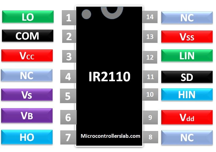
The main problem here is that the bootstrap capacitor can not be charged because of the lack of low side Mosfet.
One of the most discussed problems with IR2xxx drivers.

I guess this circuit is from an unreliable electronics amateur (site).
I always recommend to use reliable sources, like:
* original manufacturer datasheets and application notes
* Mosfet manufacturer application notes
* good tutorials (universities, professional designers...)

Other problems:
"Switching power" electronics design is not an easy task for beginners.
I miss fast capacitors and a gate resistor. Also the PCB layout plays a big role for reliable operation.
Missing capacitors and so on may cause high voltage spikes and RF noise.
So the circuit may "seem" to work ... on first sight ... but also may fail after minutes, hours... or even months.
Or it may fail in EMC compliance ... it is illegal to be operated because in worst case it may interfere with emergency radio frequency ... making emergency communication around your circuit to fail.

So it's more than "I get the expected function" to call it "correctly operating".

Klaus
 
As said, it's quite simple to switch to the low side driver section.

But the high side deriver can work too. Just ground Vs instead of leaving it floating. Also Vb can be directly connected to 12V in this case.
 
No gate drive R for transient protection in gate circuit.


Datasheet shows typical of 25 ohms.


Regards, Dana.
 
Is that the entire circuit our do you have a controller? You need a feedback loop to control the duty cycle.. Also whats the part number of the inductors your using? It sounds like your either saturating the choke or overvoltage the mosfet. You also need a load.
Thank you for your reply.
Currently, the circuit does not have a controller. The inductor I am using is a radial inductor. It does not have a part number. This is the site link that I ordered them. ( Radial Inductor link )
 

Thank you for your reply.
Currently, the circuit does not have a controller. The inductor I am using is a radial inductor. It does not have a part number. This is the site link that I ordered them. ( Radial Inductor link )
Ok that been the case then i suggest you start by researching Boost converter design to establish what current rating your choke needs to be as any old choke won't suffice. You'll need to know the maximum current your putting through it as otherwise it will saturate and likely blow up your mosfet. Once you know the current and inductance required you can select a suitable choke. Secondary will be the need for a PWM controller that looks at the output voltage your generating and controls the duty cycle to optimise the power transfer, without this you'll just blow up the mosfet or not get to the out voltage your looking for. Most controllers have the ability to drive the mosfet directly so you likely lose the IR2110 as theres no need for it.

If you do a google search for boost controllers you'll like find a controller IC that walks you through the entire design process.

.
 
Solution
Here's the saturation curve of a radial 100 uH inductor with same form factor (6x8 mm) WE-7447462101

1669554581179.png

Core saturation is one possible way to kill the transistor, another is running the converter with fixed duty cycle without sufficient load.
Better use a PWM voltage controller with current limit (preferably current mode type).
 
Status
Not open for further replies.

Similar threads

Part and Inventory Search

Welcome to EDABoard.com

Sponsor

Back
Top