Continue to Site

Welcome to EDAboard.com

Welcome to our site! EDAboard.com is an international Electronics Discussion Forum focused on EDA software, circuits, schematics, books, theory, papers, asic, pld, 8051, DSP, Network, RF, Analog Design, PCB, Service Manuals... and a whole lot more! To participate you need to register. Registration is free. Click here to register now.

Testing a 7kW Mains distribution box on full load?

Status
Not open for further replies.

cupoftea

Advanced Member level 5
Joined
Jun 13, 2021
Messages
2,669
Helped
54
Reputation
108
Reaction score
116
Trophy points
63
Activity points
14,033
Hi,

[sorry for new post....this is an entirely new approach to previous posts]

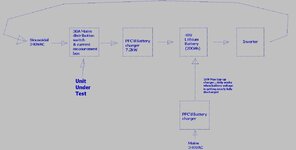
The attached is a test set-up for load test of a Mains distribution box (it contains a relay and some current measurement CTs). Its for 240VAC mains. It passes 30A.
We need to fully load it in order to test it.
As such, we wish to load it with a battery charger and battery as shown.
Do you think the inverter should be a grid tied inverter, or will it just be much cheaper to just use a non grid tied inverter as shown?

(As shown in the attached, the Grid mains does actually get used in order to make good the losses from the battery charger etc...otherwise the battery would go to full depletion, as you know)
 

Attachments

  • Mains distribution box test.jpg
    Mains distribution box test.jpg
    80.7 KB · Views: 116
Last edited:

Hi,

If you want it to be low power:

* Measure isolation with high voltage, only very low current.
* Measure power dissipation, contact and wiring resistance with high current, only very low voltage.

Klaus
 
Thanks, we cant use low voltage....the internals are supplied by Mains input SMPS's...they wont work with low mains voltage.
 

If the inverter is stand alone and can provide the 30A - then you are set to go

p.s. for less power set the inverter o/p to 200VAC, 30A heating is the same regardless of voltage

assuming the charger can handle it

the charger will decide the loop current based on batt voltage and perceived SOC, so loading the inverter externally with light bulbs ( e.g. lots of 200W ones incandecsent - or 2.4kW domestic fan heaters ) may be needed to flatten the batt somewhat to get things going ....
 
Thanks yes,
Do you think just a standard inverter instead of a grid tied one will be cheaper/simpler?
Also, yes, we have to shovel 30Amps into the battery, we cannot do less than that ...so as you imply we have the following logic algorithm....

"Logic algorithm for control"
We will need to switch in dummy loads (7.2kW's worth) when the battery voltage goes above "x" volts.......and we will also have to switch in the mains powered charger when the battery voltage goes below "y" volts.
The dummy loads must be switched out when the battery voltage goes below "x1" volts.
The mains powered charger needs switching off when the battery voltage goes above "y1" volts

I think we will throttle back the mains powered charger, as it doesnt need to charge quickly...its just to replenish the losses due to inefficiencies in the system.

There are some big chunks of hardware involved here....all of which we intend to buy off the shelf.
We were thinking of some Meanwell RPB-1600-48's in parallel for the charging.....cant find anything more powerful.
Please tell of any part numbers of kit for this? (or likely manufacturers?).

We also need it all to be controllable with the logic algorithm described above. I am wondering if this is a Labview job?

-----____----____--

Also, is there a way of omitting the battery from the test rig in the top post...?
 
Last edited:

Meanwell has a 5kW 48V charger RST-5000 - 48

the inverter needs to be able to operate as a standalone voltage source - for reasons that should be obvious.
 
Thanks, in other words, the battery would therefore be needed?

I am wondering if some system involving a controlled PFC to 400v, into a buck down to 350V , then to an inverter, then to the UUT, then back round to the pfc.....and round and round, etc etc.....could be do-able?...and make them all talk to each other so no battery needed......just some mains to put in there to replenish the system losses.......gives a good, high current test system, which works and wastes little power even though the UUT is supplied by mains level electricity, and is passing high current?
 

Status
Not open for further replies.

Part and Inventory Search

Welcome to EDABoard.com

Sponsor

Back
Top