Welcome to our site! EDAboard.com is an international Electronics Discussion Forum focused on EDA software, circuits, schematics, books, theory, papers, asic, pld, 8051, DSP, Network, RF, Analog Design, PCB, Service Manuals... and a whole lot more! To participate you need to register. Registration is free. Click here to register now.
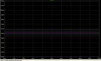
In the result of the simulation below, the collector current decreases as the temperature increases. Does anybody know why it is so? Shouldn't Ic increases as tempCo for Vbe is -2mV/C ?
In the result of the simulation below, the collector current decreases as the temperature increases. Does anybody know why it is so? Shouldn't Ic increases as tempCo for Vbe is -2mV/C ?
Without the diodes (that means: replaced by a resistor) the current Ic would remain nearly constant (only a very small increase) due to the R1 feedback effect. By the way, that is the main reason for including R1.
The Ic current decrease is caused by the diodes. Have a look on the diode Id-Vd characteristics. You will notice that there is a current increase for larger temperatures - if Vd is held constant! But this is not the case. In contrary, if the diode current Id is kept nearly constant (due to the relatively large resistance R2) the voltage drop Vd decreases correspondingly.
This effect even is doubled because of two diodes. This causes a drop of the control voltage Vbe leading to a Ic current decrease. Hope this explanation is clear enough.
This site uses cookies to help personalise content, tailor your experience and to keep you logged in if you register.
By continuing to use this site, you are consenting to our use of cookies.