electronewb
Newbie level 3
Hello, i am made a temperature controlled fan circuit, but since im new to this im not sure if i made it as optimal as i could.
I prety much used the standard recommended applications from the datasheets, and mixed it up into a circuit.
The temp. censor i use is a LM35, and i used it like this:
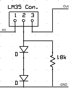
I just added a 3 pin connector for the lm35, as the actual sensor will be located a foot away from the PCB.
The circuit will run of a battery, so i put a 12 stabilized supply on it as shown here:
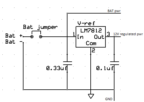
I added a jumper so i could manually disconnect, else it should be prety much as shown in the datasheet.
now as for the "fan ON/OFF" bit, i used a comperator, to set the ON/OFF reference, as shown here:
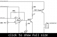
I added an LED to show when the fan should be on, just to have something to look at.
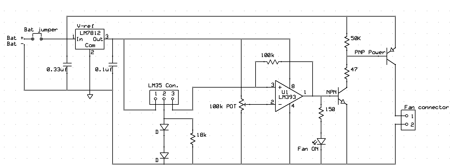
And here is the full schimatic:
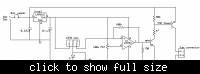
lemme know what you think")
I prety much used the standard recommended applications from the datasheets, and mixed it up into a circuit.
The temp. censor i use is a LM35, and i used it like this:
I just added a 3 pin connector for the lm35, as the actual sensor will be located a foot away from the PCB.
The circuit will run of a battery, so i put a 12 stabilized supply on it as shown here:
I added a jumper so i could manually disconnect, else it should be prety much as shown in the datasheet.
now as for the "fan ON/OFF" bit, i used a comperator, to set the ON/OFF reference, as shown here:
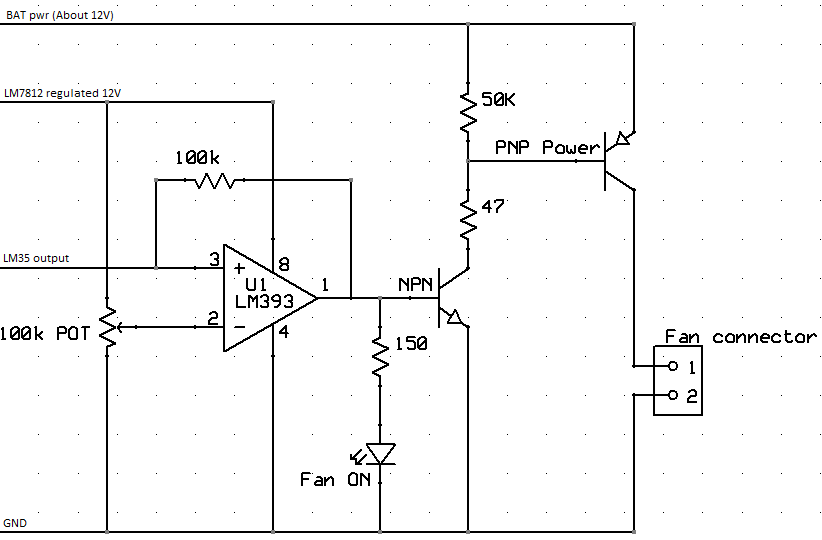
I added an LED to show when the fan should be on, just to have something to look at.
And here is the full schimatic:
lemme know what you think