Continue to Site

Welcome to EDAboard.com

Welcome to our site! EDAboard.com is an international Electronics Discussion Forum focused on EDA software, circuits, schematics, books, theory, papers, asic, pld, 8051, DSP, Network, RF, Analog Design, PCB, Service Manuals... and a whole lot more! To participate you need to register. Registration is free. Click here to register now.

Telephone Microphone Circuit Bent POTENTIOMETER HUMMING

Status
Not open for further replies.
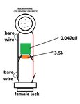
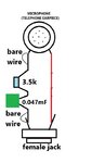
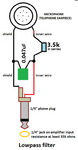
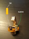
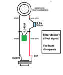
Well, I'm ran out of options. Solder a 100K resistor directly to the female guitar jack, one leg to + and another to -. Then, to make it a lowpass filter I added a capacitor, but of course nothing happened! it sound exactly the same and doesn't cut any high frequencies.

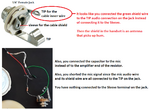
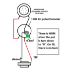
I tryed with the potentiometer once again, with the shielded cable, I put the bare with with the negative wire to the negative terminal of the mic, then solter the bare wire and the negative to the back of the pot aswell the 3rd potentiometer lug. So, STILL HUMMING, the only difference is when I solder the 3rd lug, there is no humming when open or closed, just in the middle. When that lug its not solder to the back of the pot, the humm appears as soo as I close the pot.

The shielded wire didn't make any difference, maybe just a little bit of less humming, but its still very loud. I really don't know what to do.
--- Updated ---

Maybe its the mic that has a very low reading (20.5 ohms) and I would need the right components for this kind of impedance, but I have no idea how to.
--- Updated ---

What I don't understand is why the filter works if I use a potentiometer, and doesn't work when I replace the potentiometer with a resistor of the same value (100K) plus the capacitor. It should act as if the potentiometer is closed and the filter should act.
 
Last edited:

"I added a capacitor". Series or parallel? Value of 10pF or 100uF?
Why do you want to cut high frequencies when hum is a very low frequency? Feedback squealing is a different problem.

Again:
1) Does the amplifier produce hum when there is nothing connected to its input?
2) Is there hum when only the shielded cable is connected to the amplifier's input?
 

Perhaps the mic produces a weak signal, at a high impedance? It's a good idea to run it immediately (through short wires) into a pre-amplifier. Boost it to 1 volt or so, and at a lesser impedance. Then it's less susceptible to be dominated by interference and ambient hum.

Then send it to your volume control.
--- Updated ---

The mic's ground wire should be directly connected to the pot ground and the jack ground. Your schematics make it appear otherwise.
 
Last edited:

I don't know if your old telephone earpiece has a coil and magnet so it can be a microphone. It might simply be a coil of wire that pulls on a thin piece of iron.
 

"I added a capacitor". Series or parallel? Value of 10pF or 100uF?
Why do you want to cut high frequencies when hum is a very low frequency? Feedback squealing is a different problem.

Again:
1) Does the amplifier produce hum when there is nothing connected to its input?
2) Is there hum when only the shielded cable is connected to the amplifier's input?

Hi mate.

I'll answer your questions:

1) No, the amp doesn't produce any hum when nothing is connected nor other of the equipment that I tested the mic with.
2) I've plugged the mic to different sets. My guitar amplifier, my audio interface, a mixing console. The hum is present ONLY when I install the potentiometer, with or without shielded wire. The signal itself, on its own, just the two wires directly to the female guitar jack, does NOT hum.

This mics are very popular low-fi tool for recording and live performances. Since the mic has a very "tin like" sound, it can produce feedback, so the idea is to have the option of the filter, to roll of the higher end freq. and also have a bit different sound, just that. This hum is not low freq, it is very audible, it sounds like a wave of mosquitoes!

The thing is that I've tryed to make the lowpass filter with a 0.047mF with a 3.5K resistor in series and the cuttoff freq would be around the 950Hz, wich generates the effect that I'm looking for, but nothing happened. The signal is not affected by the filter, not even a bit.

Here is a picture of the wiring I've tryed with the shieded wire:

PS: sorry that I'm not postin a schemantic, I still don't know how to read it and even less making one! haha. I'm learning.

Thanks!

Brian.
 

Attachments

  • mic low pass.jpg
    mic low pass.jpg
    52.5 KB · Views: 82

Hum is a low frequency (50Hz, 60Hz, 100Hz, or 120Hz electrical interference). Mosquitoes buzz at a fairly high frequency. You do not have any hum.
Sometimes a light dimmer causes a buzzing interference. If the mic can hear the speaker then you will have acoustical feedback howling or squealing.


You have a 3.5k resistor and low value capacitor in parallel, not in series with the 20.5 ohm microphone so the filter does nothing.
A 950Hz lowpass filter is made with a 3.5k resistor in series from the mic then a 0.047uF to ground following the resistor, and load of at least 35k ohms.
Again, you show a female jack instead of a male plug.

When you add a lowpass filter then speech is muffled and difficult to understand because all the important consonant sounds (s, f, th, sh, th etc.) are removed.
 

The example of the mosquitoes was a not so accuratte methaphore, I was intending to describe the way the hum appears, not the acctual frequency. I did the wiring as you told, but still, nothing happend (attached picture)

Didn't quite understand the part of " load of at least 35k ohms " by that you mean the reading of the mic should be at least that value?

The jack is a guitar 1/4 inch comon jack, so you can use a standard mono guitar plug with it. You get more interesting results connecting the mic to a guitar amp and thru pedals and effects.

Thanks!
 

Attachments

  • mic low pass series.jpg
    mic low pass series.jpg
    47.5 KB · Views: 77

You have the capacitor in series then it might be a highpass filter.
The mic input resistance of an amplifier is much less than 35k ohms. Then the 3.5k resistor in this filter will reduce the level of all frequencies.
To pass low frequencies but muffle high frequencies then do it like this:
 

Attachments

  • lowpass filter.png
    lowpass filter.png
    57 KB · Views: 76

Hello! It didn't work out, mate. I'm using the female jack instead of the plug. Does it make any difference? I should try different resistor values and its correspondant capacitor to see if it works.
 

Attachments

  • ddd.jpg
    ddd.jpg
    23.3 KB · Views: 68

Mic cables have plugs and amplifier inputs have jacks.
I do not know why yours are backwards.

The RC lowpass filter is very simple so its affect is gradual. 950Hz is reduced -3dB which is just a little less loud. 1900Hz is -6dB which is reduced a little more. 9500Hz has much lower loudness but is still heard.
 

Attachments

  • jack.png
    jack.png
    135.3 KB · Views: 71

Mic cables have plugs and amplifier inputs have jacks.
I do not know why yours are backwards.

The RC lowpass filter is very simple so its affect is gradual. 950Hz is reduced -3dB which is just a little less loud. 1900Hz is -6dB which is reduced a little more. 9500Hz has much lower loudness but is still heard.

I don't know, mate. That is the way this thelephone mics are made. I think they are mostly used with guitar amps. This is an example of the filter pot


There is your hum problem. The wires inside a telephone handset that feed its earphone are not shielded!
The jack and pot should be in the other end of the handset with very short wires so they are very close to the earphone that is used as the mic.
That also explains why there is a jack and not a plug.

But I'm using shielded wire! I'll attach the picture (you see that I solder the resistor and capacitor the way you indicate). And I still don't understand why the guy in the video make it work propperly! the wires go from the earpiece to the mouth piece used to be and he has no hum at all when he turns down the filter pot. I understand that by reducing the lenght of the shielded wire I can reduce the hum, thats because the wires act like an antena, am I right? even tough its shielded.
 

Attachments

  • 20201026_114309 (1).jpg
    20201026_114309 (1).jpg
    188.4 KB · Views: 73

Look here:
--- Updated ---

Moderator; there is another thread about this problem in Elementary Circuit Questions. Please merge them together if possible.
 

Attachments

  • telephone mic hum.png
    telephone mic hum.png
    351.1 KB · Views: 77

Look here:
--- Updated ---

Moderator; there is another thread about this problem in Elementary Circuit Questions. Please merge them together if possible.
Sorry! there is a mistake in the perspective of the picture. Yes, I had everything wired correctly.

Here is a picture of the kind of jack that I'm using. There is a 3rd lug but I think is for other kind of use. I've also tested the wiring in a common 2 lug jack, but it was the same.
 

Attachments

  • WhatsApp Image 2020-10-26 at 19.16.35.jpeg
    WhatsApp Image 2020-10-26 at 19.16.35.jpeg
    175.7 KB · Views: 66

Adding to the jack confusion, your jack has a switch in it which might be connected wrong.
Your long unshielded red wire and long resistor wires are antennas that pickup hum.
 

Hi,

your wiring in post#33 is different to the schematic in post#28.
The capacitor is at the wrong side of the resistor.
The capacitor needs to be at the plug side of the resistor not at the mic side of the resistor.

Klaus
 

Ok, we are now talking about two separate problems:

1) The Hum: This is only present when I use the POTENTIOMETER.

2) The filter without potentiometer: There is no hum here, the problem now is that the filter doesn't work at all.

The only thing that I can think about is that the low reading of the earpiece is causing all the trouble.
--- Updated ---

Hi,

your wiring in post#33 is different to the schematic in post#28.
The capacitor is at the wrong side of the resistor.
The capacitor needs to be at the plug side of the resistor not at the mic side of the resistor.

Klaus
Hi Klaus! its a wrong perspective of the picture! here are the two wirings the I've tested so far and its problems:
 

Attachments

  • lowpass filter.png
    lowpass filter.png
    67.5 KB · Views: 83
  • mic with pot.png
    mic with pot.png
    52.7 KB · Views: 71
  • lowpass filter.png
    lowpass filter.png
    67.5 KB · Views: 68
  • mic with pot.png
    mic with pot.png
    52.7 KB · Views: 62

Hi,

It's not clear how you connected the pot.
Please post a photo.

Klaus
 

Hi,

It's not clear how you connected the pot.
Please post a photo.

Klaus
Sorry, that is the back of the pot.

VIEW FROM THE BACK OF THE POTENTIOMETER:
- Mic possitive to the LEFT lug of the pot
- From the middle lug of the pot to the tip lug of the jack.
- Mic negative to the case of the pot, a wire from the case of the pot to the sleeve lug of the jack.
- The capacitor is wired in the middle lug of the pot to the case of the pot.
- Right lug of the pot is free, if I ground it to the case of the pot, for some reason the filter doesn't work and the pot acts as a volume pot.
 

Status
Not open for further replies.

Similar threads

Part and Inventory Search

Welcome to EDABoard.com

Sponsor

Back
Top