mleem
Newbie level 3
If I need to achieve a certain SLL from a (square) planar array, I first was working a linear array of the same width. I achieved the result I wanted, but was unsure how to extend this to the planar array.
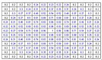
I've seen it done where the distribution was determined instead by using the largest dimension of the array (in this case, the diagonal) and then just rotating this around the whole array. The problem with this is that on the principal planes, you no longer get the SLL you want since it is shorter than the rotated distribution. You would have to use a much lower Taylor to achieve this, but that makes an unnecessarily large HPBW.
If I determine the distribution from the principle planes, and rotate it, what tapering would go on the corner elements? Or, would I need to modify the distribution for each angle to the length?
