Continue to Site

Welcome to EDAboard.com

Welcome to our site! EDAboard.com is an international Electronics Discussion Forum focused on EDA software, circuits, schematics, books, theory, papers, asic, pld, 8051, DSP, Network, RF, Analog Design, PCB, Service Manuals... and a whole lot more! To participate you need to register. Registration is free. Click here to register now.

T power divider ; Ansoft Designer

Status
Not open for further replies.

dynamicdude04

Junior Member level 1
Joined
May 31, 2008
Messages
15
Helped
0
Reputation
0
Reaction score
0
Trophy points
1,281
Activity points
1,368
power divider ansoft

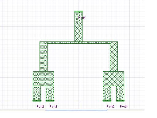
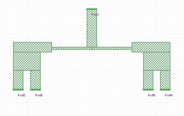
Whenever you change the pattern of your patches or strips in a T power divider your results are changed why??

Dimensions are kept constant still the results are changed???

why???
 

t power divider

Specifically, what pattern, dimension and results are you referring to ?


The results were as follows


Now the dimensions of the patches are same but but theyve been aligned differently as follows


Now the results are different !!!!!!!


i need a solid reason ??why are the results changing???
Thanx
 

Hi

I guess that your results come from an EM-simulation. In that case I do not see it as odd. Your structure is connected differently between the two setups and at 3-4 GHz the allignment of your conductors are not arbitrary.

The first case have two lengths and the second here the length is shorter but wider because they are put right next to each other.

Regards
 

I cant figure out how to verify that my power is dividing correctly

i calculated the p11= s11*s11 graph vs freq and the rest s22*s22 ,s33*s33

and the values at my freq(3.5ghz) were for p11 0 and p22 0.27 ,p33 0.27, p44 0.27 p55 0.27

I cant figure out why the p11 is coming zero? where could be the fault???

Added after 1 minutes:


Sorry but what are you trying to do actually ?

If i'm not wrong, you should be looking at S12, S13,S14 and S15 to verify your power divider.

I think you might need to read up some basic about microwave first.
 

For a power divider our s11 ,s22 s33, s44 ,s55 should all be zero isnt that so??

while S parameters only telll you about incident and reflected powers

but what if a person wants to find how much power was input on port1 and how much of it came out at port 2,3,4 or 5

i calculated this by using the above formula which i got from ansoft designer manual for optim tee ??

if this is not the proper way then how should i verify my power divider that its working properly????

what should be my S parametrs if S parametes are used to check it???
 

Hi

I think you should check out Pozars exellent book "Microwave Engineering". The section about couplers is very useful for your problem.

You device cannot be lossless, reciprocal and matched at all ports at the same time.

The S-parameters tell you how much power is reflected and how much is transfered, i.e. S21, S31....

But I think you should check some litterature first.

Regards
 

should i see the coupler stuff or the S parameter stuff??

what do u recommend?
 

Hi

I would say both....I guess you do not have a lot of experience?
 

If you have no time, then just read coupler.

Else, read both if not more...
 

Okz, Thanx alot!!! Im goig to find my book see whats going on..............


appreciate your help!!!!
 

tyassin said:
You device cannot be lossless, reciprocal and matched at all ports at the same time.

For thread starter information,

A Wilkinson Power Divider is able to achieve the above mention.
 

Hi

Well not really, the isolation resistor is making the Wilkinson lossy, although only between port 2 and 3.
 

in my view wilkinson works good under low frequencies At high frequencies like mine (3.5Ghz for wimax) we have to use a T junction

Resistors are lumped elements and use have to use distributed elements at high frequencies above 500mhz

Added after 52 seconds:

After all wilkinson boy uses a resistor
 

Lossless , Reciprocity and Matched Network at the same time is not possible

U have to compromise on one thing
 

Seems like you have read up.

Anyway, I have use wilkinson divider up to 11GHz.
You are right that resistor need more attention at higher frequency.
 

Oh thats great !!!

Were the measured results as expected ?
 

slight deteriorate but still acceptable.
 

Status
Not open for further replies.

Part and Inventory Search

Welcome to EDABoard.com

Sponsor

Back
Top