Continue to Site

Welcome to EDAboard.com

Welcome to our site! EDAboard.com is an international Electronics Discussion Forum focused on EDA software, circuits, schematics, books, theory, papers, asic, pld, 8051, DSP, Network, RF, Analog Design, PCB, Service Manuals... and a whole lot more! To participate you need to register. Registration is free. Click here to register now.

[SOLVED] Symmetric PSU LM338 fault - Negative rail drops voltage

Status
Not open for further replies.

Rompeolas

Newbie level 3
Newbie level 3
Joined
Oct 25, 2014
Messages
3
Helped
0
Reputation
0
Reaction score
0
Trophy points
1
Visit site
Activity points
29
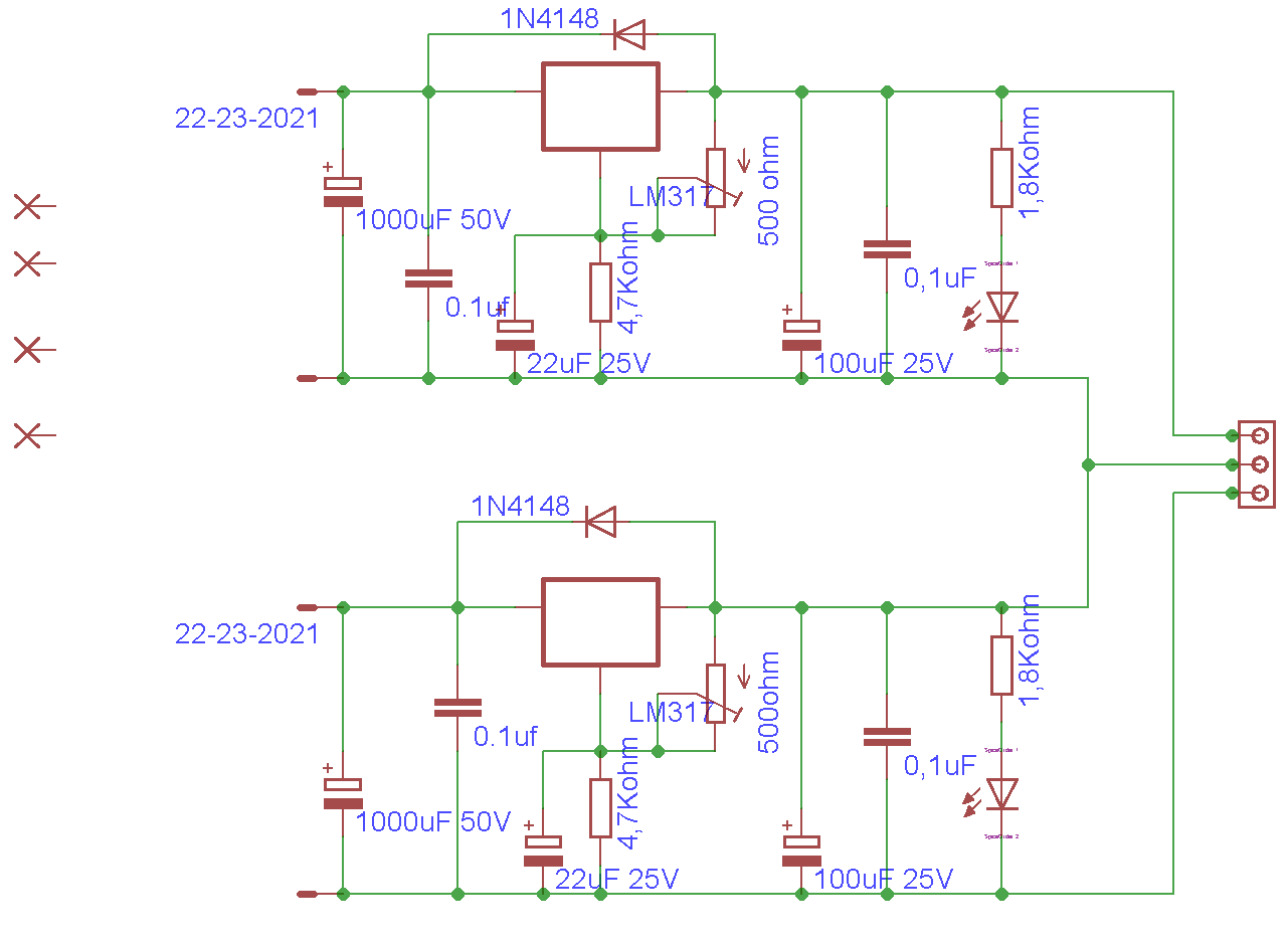
Hello,

I am making a dual regulated PSU with LM338 to get +/-17V.
Each rail is fed with one secundary of the main transformer.

The thing is that if I feed just one rail (any of them), the rail works and can be regulated.

If I feed both rails at the same time, the negative rail drops voltage to around 3V and the negative regulator becomes really hot.

Things I have already tried:
- LM317 with same result.
- Removed and measure the components and the readings are fine.
- Measure Ohm between paths and no shortcut has been found.
- Lift earth from the PCB

Any advise to where to look at?

Thank you very much..!!

8770278200_1414263229.png
 

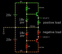
To be a true bipolar +/- supplies, your negative section needs to be 0V ground referenced.

Moreover the regulating portion needs to resemble a PNP transistor. As in this schematic.


A 337 IC can perform the job of negative supply regulation.

- - - Updated - - -

http://www.circuitstoday.com/dual-adjustable-power-supply-using-lm-317-lm337
 

The circuit would work if both transformer secondary windings and connected rectifier circuits are completely separated. Apparently they aren't.
 

Thank you very much for answering.

Each secundary feeds one square metal bridge rectifier wich are screwed to the chassis.
The middle pin of the output connector is also connected to the chassis and the chassis is connected to the earth of the mains plug.

I have made some changes in red to the drawing.

Fuente_SYM_2_railes_schematic1.1.gif


I already have the PCB of this circuit, and would like to give it a chance before making another one with LM317 and LM337.

Thank you very much again.
Best regards
 

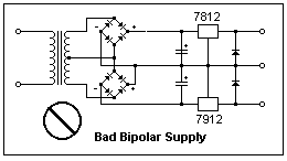
There is a not-very-obvious gotcha when you arrange diode bridges this way.

Look for a short circuit going through two diodes and your negative 317 IC. It goes through the entire secondary winding, during one half of the cycle.

It would happen even if you were to use a 337 negative regulator.

3069054600_1414303414.png


I'll bet this is the cause of your voltage drop and temp rise on your negative 317.
 

If you have a centre tapped transformer, or you connect up the secondaries to make one, then if you put the bridge across the outer connections, then the centre tap then becomes the half way voltage or earth. So you then run a + regulator in series with the + from the bridge and a - regulator from the negative of the bridge. It saves a bridge rectifier.
Frank
 

The post #4 circuit shows completely separated input supplies and is expected to work.

I see two possible explanations:
- the input supplies aren't separated as discussed in post #5 and #6
- the problem only occurs with output load and is actually an overload problem

Related to the second case (load related problems), there's a special point that some voltage regulators don't like the output being pulled into reverse polarity. This can happen with a dual supply either during start-up or by output overload and results apparently in an internal regulator latch-up. I have seen this problem only with fixed regulators that have no current limiting resistor connected to the reference pin, but I won't exclude that it can happen with adjustable regulator. A diode blocking reverse output helps in this case.
 

First of all, I would like to thank you all for your time and knowledge.

I measured the rectifier bridge and tested OK, but anyway I tried different ones. Nothing changed.

I tried with 2 differents transformers, one for one rail, and another transformer for the other rail. The output capacitor of the negative voltage had fireworks... so funny.

I measure Ohms through both the secundarys and it has a shortcut.

I have tried another transformer and it works..!!

Once again, thank you very much for helping.
 

Status
Not open for further replies.

Similar threads

Part and Inventory Search

Welcome to EDABoard.com

Sponsor

Back
Top