Vermes
Advanced Member level 4
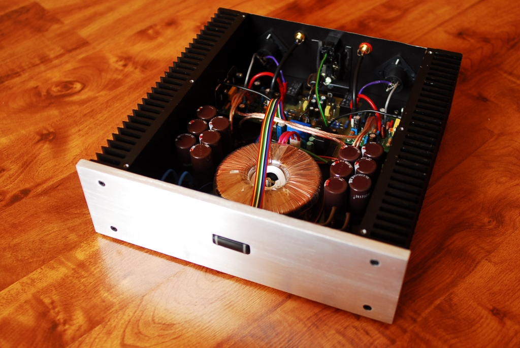
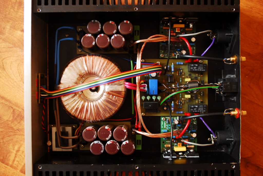
It is a power amplifier based on SymAsym modules. Power of transformer is 200VA and voltage of 2x28V. Power supply consists of two rectifier bridges 8A and ten capacitors with a capacitance of 4700uF/50V Nippon Chemi-Con. Capacitance on each rail is approximately 23 500uF. Under the PCB, in parallel under each bigger capacitor, there is a smaller one 100n. Safety fuses 3,15A are previous power modules. Paths are flooded with tin.

Power module is SymAsym. Power amplifiers are based on transistors 2SA1943/2SC5200. Transistors were paired. Transistors of small power were connected with a shrinkable tube for the thermal coupling. 1% precision resistors were applied in this project. Transistors were screwed with M3 screws, after applying silicone pads and thermoconductive paste. Quiescent current was set to 15mV.
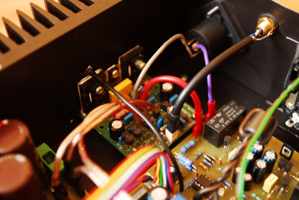
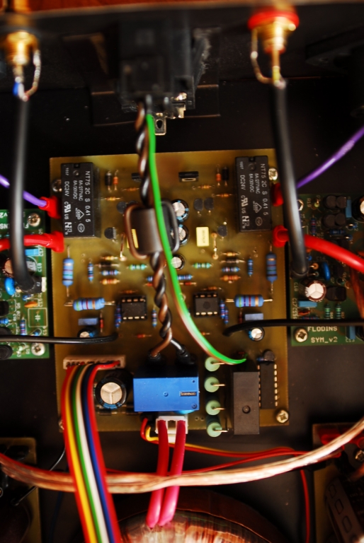
There is also a protection against constant voltage at the output, against high temperature (a relay disconnects the speakers at 80 degrees Celsius). All that is done on comparator LM393. Fast disconnection of the speaker is also available after loss of voltage on the transformer and delayed turn on at running the amplifier (about 3 second delay). One protection goes to one power module.
Softstart of the transformer is also placed on that PCB. There is a switch on the front panel, implemented on flip-flop CD4013. It provides AC voltage to the transformer's soft start through switching a relay. The main switch is located on the back of the housing.
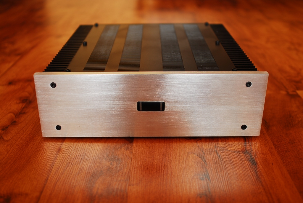
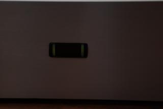
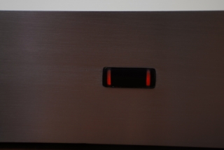
There is a switch on the front panel. That switch consists of two red LEDs and two green LEDs. When turned on, red LEDs light for 3 seconds – it is the delay of speakers. Uncorrect operation of the amplifier (constant voltage, too high temperature) is indicated by those two diodes. After few seconds, red LEDs go off and if the power amplifier operates correctly, green LEDs light up.
Housing of the amplifier is based on two heat sinks with dimensions of 300x85mm, front panel with a thickness of 10mm. The rest is made of steel sheet. Front panel was brushed with a sandpaper (100). There are chinches in the back input, speakons at the output and a socket connected with the switch and fuse. Housing is screwed using M4 screws. Sheets on bottom, back and top were painted black in powder method.
Pictures:


Link to original thread - Symasym - końcówka mocy