Continue to Site

Welcome to EDAboard.com

Welcome to our site! EDAboard.com is an international Electronics Discussion Forum focused on EDA software, circuits, schematics, books, theory, papers, asic, pld, 8051, DSP, Network, RF, Analog Design, PCB, Service Manuals... and a whole lot more! To participate you need to register. Registration is free. Click here to register now.

[SOLVED] Switching LM317 on/off

Status
Not open for further replies.
Hi,

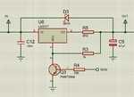
I can not see how the LED current can still be 50mA.

Before you talked about a voltage divider... Where is it? And what values?

Klaus
 

Ok so my power supply is 30v (600W)
My LEDs are rated 3.2 to 3.6v (so in my calculation I will always choose worse case scenario and choose 3.6v)
The LM317 needs 1.25v + 3v headroom
So in total for 7 leds I need 29.45v hence why the power supply is 30v


While testing out this circuit, I only have 30v available and to replicate a 5v signal coming from a micro controller that will be controlling my transistor, I used a simple voltage divider. The values are 57k (47k and 10k in series) and 10k giving me an output of 4.48V (relatively close to the 5V that I will be getting from my micro controller).


When I connected the circuit as in my attachment above here are my findings:

  • transistor ON (ie: being triggered by 4.48v) on power up - the LEDS light up nice and bright (drawing the expected 600mA) and immediately start to dim down until the current being read from an analog gague (thus cannot be accurate) is close to 0 (earlier I just said 50mA) but this was for the fact that I could still see some LEDs lit up but almost OFF.
  • transistor OFF (ie: left floating) on power up - the LEDS light up nice and bright - nothing else happens
 

Here's a slow-start circuit with the addition of C1.
The value of C1 determines the start time.

Capture.PNG
 

AHA Hold on! My circuit is wrong! My capacitor is wrongly connected from base to gnd not collector to gnd. I will have to wait 2 hrs until I can try it again! Thanks for the moment. If it doesn't work after this fix I will take a video and show you how its acting up!
 

Right so I had the time to test out both PWM and the most recent schematic and here is what happened:

With the capacitor, I still had weird behaviour whereby the LEDs where doing a slow stop rather than a slow start.
When I tested PWM I was very happy and satisfied as I could control them super smoothly and I am going to settle on that solution.

Thanks crutschow for your simulation and everyone who contributed. Much appreciated. For anyone coming after here is the final circuit which worked.

I have 13v across R3 when the LEDs are OFF and 0v when they are ON
I have 0.758v across from the collector to the emitter when the LEDs are OFF
 

Attachments

  • pwm led constant driver.png
    pwm led constant driver.png
    35.2 KB · Views: 108

Status
Not open for further replies.

Similar threads

Part and Inventory Search

Welcome to EDABoard.com

Sponsor

Back
Top