Continue to Site

Welcome to EDAboard.com

Welcome to our site! EDAboard.com is an international Electronics Discussion Forum focused on EDA software, circuits, schematics, books, theory, papers, asic, pld, 8051, DSP, Network, RF, Analog Design, PCB, Service Manuals... and a whole lot more! To participate you need to register. Registration is free. Click here to register now.

Switching Capacitor to floating load

Status
Not open for further replies.

Moonwalker

Member level 2
Joined
Jul 10, 2006
Messages
43
Helped
1
Reputation
2
Reaction score
1
Trophy points
1,288
Activity points
1,622
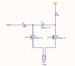
I have a capacitor (slowly charging) and need to discharge it to a floating load. I am currently using a double pole relay to do this but would like to convert the circuit to mosfets. I have attached the circuit but have some doubts that it would work properly.
Any help?
 

Attachments

  • Capswitch.jpg
    Capswitch.jpg
    254.5 KB · Views: 112

It is not clear how it is supposed to opperate, but at first sight the current at Q1 should flow across its antiparallel diode ( not shown at the above symbol ). In addition, I would recommend to add a small resistor in series with the lamp, just to limit the surge current that could stress either the mosfet or the capacitor itself. Had you made simulation of that circuit in software ? It is quite simple, worthy to check.
 

If the load is actually floating (no other connections), a single switch will do. If not, you need to know the load voltage range enforced by the other connections.

Consider that technical MOSFET have substrate diodes and can only disconnect one polarity, e.g. positive Vds for NMOS.

The right question is which gate voltage range must be generated by the driver to switch the MOSFET(s) properly on and off. Also where to use NMOS or PMOS and how to connect the transistors.
 

Ok my aim is to discharge the capacitor through the load. The lamp actually is a pyro igniter and I have several of them connected near each other - separate circuits of-course.
The current circuit uses double pole relays and works fine but I am concerned about the high discharge current since the relays are only rated at 3A.

So back to the above circuit, Q2 probably should be a P channel. But I don't wish to remove Q1. Is there any other way to connect a mosfet so that it only switches when intended?
 

So back to the above circuit, Q2 probably should be a P channel. But I don't wish to remove Q1. Is there any other way to connect a mosfet so that it only switches when intended?

Hi,

Could you use one signal, i.e. input high = nmos gate high (on) and pmos high (off), input low = nmos gate low (off) and pmos low (on)?
 

This simulation is a slight modification of your schematic. It's up to you whether it fits the overall control system you're using.


Thanks but I would definitely not have the LOAD always connected to the HI side (even through R1) for safety reasons.
So a P mosfet on the high side is a must but I would still like to disconnect the LO side of the load too.
 

Thanks but I would definitely not have the LOAD always connected to the HI side (even through R1) for safety reasons.
So a P mosfet on the high side is a must but I would still like to disconnect the LO side of the load too.

When the control signal goes high, the NPN & PNP turn on, discharging the capacitor rapidly through the load. It works in simulation but it's up to you to adjust values, add components, etc., so that it operates properly in your system.


The 5k resistors are needed so that base (or gate) terminals are not floating. If they are left floating then they can be influenced by ambient electrical noise, mains hum, static charge, etc. These things can cause false triggers.

The 5 ohm resistor is a good idea, to limit unintended current bursts.

The 40 ohm resistor represents unknown resistance in your wire run. It should be low instead of high. However it should not be so low that it draws overmuch current from your control unit. This is an area for experimentation.
 
Thanks again.
This is exactly what I had in mind but still have a dilemma between BJTs and mosfets.

BTW - what simulation sw is that?
 

Thanks again.
This is exactly what I had in mind but still have a dilemma between BJTs and mosfets.

BJT is not so affected by ambient electrical noise, mains AC hum, static charge, etc.
Another option is SCR's. Also darlington arrangement of NPN's.

So far you have used relays, which is the safe thing with a load like pyro igniters. Relays are pretty much immune to false triggers. When you consider substituting solid state components, the possibility of false triggers takes a big jump upward. You should do everything to prevent a chance of false triggers. Perhaps additional safeguards are necessary. My simulation only shows simple theoretical operation.

It's a good idea to install led's, to tell you if the transistors are conducting unwanted current.

BTW - what simulation sw is that?

Falstad's animated interactive simulator. Free to download and use at:

www.falstad.com/circuit

I find that its mosfet model usually requires very high voltage to the gate, in order to turn it on fully. That is the reason I often use bjt's instead.
 
Status
Not open for further replies.

Part and Inventory Search

Welcome to EDABoard.com

Sponsor

Back
Top