Continue to Site

Welcome to EDAboard.com

Welcome to our site! EDAboard.com is an international Electronics Discussion Forum focused on EDA software, circuits, schematics, books, theory, papers, asic, pld, 8051, DSP, Network, RF, Analog Design, PCB, Service Manuals... and a whole lot more! To participate you need to register. Registration is free. Click here to register now.

Switch Positive and Negative voltage with TTL signal

Status
Not open for further replies.

helium4amc

Newbie level 2
Joined
Dec 26, 2007
Messages
2
Helped
0
Reputation
0
Reaction score
0
Trophy points
1,281
Activity points
1,309
Hi all, this is my first post here, but the boards have been extremely useful over the years!

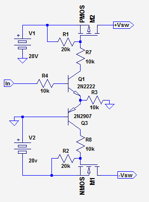
I am running a test in which I need to switch positive and negative power lines on simultaneously, which will be in the range +/-13 V to +/-28 V. I would like to drive the switches with a single 5 V input (from an Arduino). The test units will draw ~350 mA from each supply (although the current drain on positive and negative is not quite the same).

My first thought was to use a couple of MOSFETs, but I have played around in Proteus and can't get them to both switch (my experience with them is pretty small).


I am open to any suggestions for ways of doing this and would love to know why my circuit above isn't working (apart from the obvious fact that I clearly have no idea what I am doing!).

Thanks in advance!

Andrew
 

Your Q1 symbol appears upside-down (based on the direction of its internal diode).

It will help if you were to experiment by applying various volt levels to the gate of the mosfets. A potentiometer is a handy method to deliver the entire range between supply + and supply -. This will let you discover what bias voltage causes what response in the mosfets.

Also experiment with placing Nmos or Pmos in the positive or negative side of your circuit.

Also experiment with placement of the load in relation to the mosfet. The load can be closer to 0V ground, or closer to the supply rail.

Also experiment with using transistors as well as mosfets.

These experiments will tell you what is the most satisfactory arrangement to switch your loads.
 
Below is a circuit that should do what you want.
The MOSFETs can be just about any of sufficient voltage and current rating (at least 50V and 1A).
The trick to the circuit is to use a grounded -base PNP transistor to translate the positive input signal to a negative control voltage.

Plus-Minus Switch.PNG
 
Last edited:
BradtheRad and Crutschow thank you both very much for your quick help!

Crutschow, that circuit worked perfectly in simulation and I will build it up tomorrow (components are all in the lab) and hopefully get it working!

Brad, thanks for the advice, I would really like to improve my knowledge of transistors, FETs etc. and how to implement them in a circuit. Could either of you suggest a good book/online course/anything that would be a good start? I have seen loads online, but there are so many it is hard to pick one!

Thanks again,
Andrew
 

The circuit in post #3 applies nearly 28 Vgs to both MOSFETs. To control the gate voltage, you might modify it like this

switch.png
 

The circuit in post #3 applies nearly 28 Vgs to both MOSFETs. To control the gate voltage, you might modify it like this
....................
Yes, I forgot about maximum Vgs.
Below is an alternate modification to keep Vgs below 20V with 28V supplies.
Note that the MOSFETs should be logic-level type to insure they are fully on with 13V supplies.

7853995900_1442785290.png
 

Status
Not open for further replies.

Similar threads

Part and Inventory Search

Welcome to EDABoard.com

Sponsor

Back
Top