neazoi
Advanced Member level 6
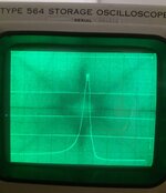
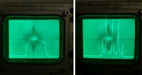
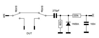
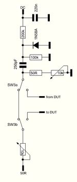
Hi, I am sweeping across different IF filters with this circuit and all of my multi-pole crystal, ceramic, or mechanical filters show a huge passband ripple. I tested several of them:
The ripple is always there, no matter if I reduce the power applied to the filter or if I load the detector input to 50 ohms.
Why is that happening on some filters and on some other not?
- two 455KHz crystal filters, gave huge passband ripple.
- two 455KHz ceramic filters multi-pole, gave huge passband ripple.
- two 455KHz mechanical filters multi-pole, gave huge passband ripple.
- a single 455KHz ceramic resonator, gave no ripple.
- a single 3.6MHz crystal gave no ripple
- a single 7.1MHz ceramic resonator gave no ripple.
The ripple is always there, no matter if I reduce the power applied to the filter or if I load the detector input to 50 ohms.
Why is that happening on some filters and on some other not?