Continue to Site

Welcome to EDAboard.com

Welcome to our site! EDAboard.com is an international Electronics Discussion Forum focused on EDA software, circuits, schematics, books, theory, papers, asic, pld, 8051, DSP, Network, RF, Analog Design, PCB, Service Manuals... and a whole lot more! To participate you need to register. Registration is free. Click here to register now.

supply voltage monitor

Status
Not open for further replies.

franticEB

Full Member level 3
Full Member level 3
Joined
May 10, 2010
Messages
153
Helped
1
Reputation
2
Reaction score
2
Trophy points
1,298
Visit site
Activity points
2,551
Hi all,
I would like to design a circuit to monitor the supply voltage of a board.

Suppose that is 50Volts, I wish I had reported variations of + / -5% of the latter.

The circuit for reading shold be composed by the microcontroller + AD connected trough spi interface and feed by dcdc converter for various voltage
(50Volts --->|||--->3,5,15volts).


Important that monitor circuit and power supply are isolated between them.

Could you help me with some ideas,schematics and with the research of components to be used?
thanks
 

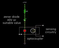
When you want isolation, an optocoupler is a common technique.

The internal LED lights up in proportion to current through it. The internal photosensor reacts by changing its resistance accordingly.

To obtain expanded scale measurement, put a zener diode in series with your source. Then the LED will show greater variations in brightness, as the supply voltage changes. This should allow you to detect + or - 5% variation.

Example:


When you want isolation, an optocoupler is a common technique.

The internal LED lights up in proportion to current through it. The internal photosensor reacts by changing its resistance accordingly.

To obtain expanded scale measurement, put a zener diode in series with your source. Then the LED will show greater variations in brightness, as the supply voltage changes. This should allow you to detect + or - 5% variation.

So how could i measure this variation by AD converter or by microcontroller? Is it so sensitive? Could you explain me better your idea?
 

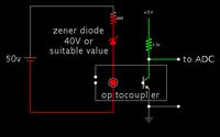
Here is a more complete schematic:


The output level (at right) will drop with an increase in the applied volt level (at left). Your sense software must invert this behavior.

The optocoupler will give a roughly linear response to the applied volt level. Your sense software will need to account for this. You'll have to experiment with resistor values, to obtain the best operating range. At no time should you expose the devices to overmuch current.

Some more information at:

https://www.electronics-tutorials.ws/blog/optocoupler.html

https://www.technogumbo.com/projects/Learning-to-Use-an-Optocoupler-or-OptoIsolator/
 

Status
Not open for further replies.

Similar threads

Part and Inventory Search

Welcome to EDABoard.com

Sponsor

Back
Top