pancho_hideboo
Advanced Member level 5
- Joined
- Oct 21, 2006
- Messages
- 2,847
- Helped
- 767
- Reputation
- 1,536
- Reaction score
- 733
- Trophy points
- 1,393
- Location
- Real Homeless
- Activity points
- 17,490
Summation Point Movement in CT-Delta-Sigma-ADC
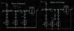
See a left block diagram in attached first figure.
This is a simple 2nd-order continuous time delta-sigma ADC of Feedback structure with a feedback path for excessive loop delay compensation.
This compensation path is implemented by DAC3.
In this block diagram, I assume passive summation before quantizer. So gain K is required before quantizer.
I implement this gain equivalently by decreasing a distance of thresholds of quantizer without using gain block K.
When I implement this block diagram using Mathworks Simulink, I can get almost same SQNR as a result of Mathworks MATLAB simulation using "simulateDSM()" in Schreier's Delta-Sigma Toolbox.
Next see a right block diagram in attached first figure.
Feedback path via DAC3 is equivalently moved to before integrator.
When I implement this equivalent block diagram using Simulink, I can not always get same SQNR as a result of MATLAB simulation.
A degradation is about 10dB.
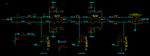
See attached second figure.
This is a behavioral model using Verilog-A for passive summation.
Here I use three current DACs.
If I simulate this Verilog-A model using Cadence Spectre with "errpreset=conservative", I can get almost same SQNR value as a result of MATLAB.
This result is same as Simulink simulation.
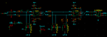
See attached third figure.
This is a behavioral model using Verilog-A for euivalent summation point movement.
Here I use two current DACs and one voltage DAC.
When I simulate this Verilog-A model using Cadence Spectre, I can not get same SQNR value as a result of MATLAB.
Degradation is aboout 10dB.
This result is same as Siumlink simulation.
Why can not I get SQNR without degradation ?
See a left block diagram in attached first figure.
This is a simple 2nd-order continuous time delta-sigma ADC of Feedback structure with a feedback path for excessive loop delay compensation.
This compensation path is implemented by DAC3.
In this block diagram, I assume passive summation before quantizer. So gain K is required before quantizer.
I implement this gain equivalently by decreasing a distance of thresholds of quantizer without using gain block K.
When I implement this block diagram using Mathworks Simulink, I can get almost same SQNR as a result of Mathworks MATLAB simulation using "simulateDSM()" in Schreier's Delta-Sigma Toolbox.
Next see a right block diagram in attached first figure.
Feedback path via DAC3 is equivalently moved to before integrator.
When I implement this equivalent block diagram using Simulink, I can not always get same SQNR as a result of MATLAB simulation.
A degradation is about 10dB.
See attached second figure.
This is a behavioral model using Verilog-A for passive summation.
Here I use three current DACs.
If I simulate this Verilog-A model using Cadence Spectre with "errpreset=conservative", I can get almost same SQNR value as a result of MATLAB.
This result is same as Simulink simulation.
See attached third figure.
This is a behavioral model using Verilog-A for euivalent summation point movement.
Here I use two current DACs and one voltage DAC.
When I simulate this Verilog-A model using Cadence Spectre, I can not get same SQNR value as a result of MATLAB.
Degradation is aboout 10dB.
This result is same as Siumlink simulation.
Why can not I get SQNR without degradation ?
Attachments
Last edited: