Continue to Site

Welcome to EDAboard.com

Welcome to our site! EDAboard.com is an international Electronics Discussion Forum focused on EDA software, circuits, schematics, books, theory, papers, asic, pld, 8051, DSP, Network, RF, Analog Design, PCB, Service Manuals... and a whole lot more! To participate you need to register. Registration is free. Click here to register now.

Suitable TRIAC for inductive load application?

Status
Not open for further replies.

alexxx

Advanced Member level 4
Joined
Apr 17, 2011
Messages
1,013
Helped
273
Reputation
552
Reaction score
270
Trophy points
1,383
Location
Greece
Visit site
Activity points
7,936
Triac input=230V@50Hz. The load is a a flyback converter and will draw max 90mA@230V or 150mA@150V.

150mA inductive load means I need at least 1.5A RMS on-state current right? Also from what I read sensitive gate is better, but if I use a non sensitive triac and add a resistor 1K between G and T1, I'm OK. And also if I use a 4q triac (instead of a 3q), I need to use an RC snubber.

Are those correct conclusions? Are there any other aspects I should take into account? The drive circuit is from MOC3023 optotriac datasheet.
 

No idea why you consider a flyback converter as inductive load? But you should be aware of a large inrush current by the filter capacitor, and a RC snubber should be used in any case.
 
  • Like
Reactions: alexxx

    alexxx

    Points: 2
    Helpful Answer Positive Rating
Sorry for the question but what is the difference between the 4q and a 3q triac?
 

No idea why you consider a flyback converter as inductive load
Because there is an IC that switches on a transformer which is in series with power line, I thought that is inductive load. Maybe I am wrong. In any case, according to specification (150mA), an 1 Amp TRIAC should be OK, isn't it? What about the 1K resistor between G and T1? Should this be used as well?
 

Because there is an IC that switches on a transformer which is in series with power line..

A transformer? I think you are confusing it with a common-mode inductor, which is a component of the EMI filter. From a load point of view, that device is completely transparent.

- - - Updated - - -

Sorry for the question but what is the difference between the 4q and a 3q triac?

The Triac can be fired in four possible modes:

Quadrant I (main terminal 2 positive, gate positive)
Quadrant II (main terminal 2 positive, gate negative)
Quadrant III (main terminal 2 negative, gate negative)
Quadrant IV (main terminal 2 negative, gate positive)

These definitions were taken from Teccor's Application Note AN1008
 

schmitt trigger said:
A transformer? I think you are confusing it with a common-mode inductor, which is a component of the EMI filter.
Hi schmitt trigger! I am not talking about common mode choke. It is an off line switcher that gets supply from the TRIAC output. It is a TNY268 SMPS IC, which choppes on a flyback transformer via an internal mosfet and supplies an MCU from the secondary side. I thought that I should consider this as "inductive load". So this "MCU" reads mains voltage coming from the TRIAC and it takes appropriate decisions based on that voltage. This is why I need to output 230V or 150V AC from the TRIAC.

By the way, if you have any comments about post#4, I would be glad to listen to any proposals.

Alex
 

Inductive load essentially means lagging sinewave current.

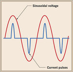
When the AC mains is rectified and capacitor-filtered, the resultant input current waveform is not exactly a lagging sinewave.
It is a pulsed waveform like the shown in the attached image.

**broken link removed**

Therefore, ensure that you trigger the Triac for at least 90 degrees after each zero crossing to ensure latching.
 
  • Like
Reactions: alexxx

    alexxx

    Points: 2
    Helpful Answer Positive Rating
schmitt trigger, unfortunately there is something wrong with the file attached, I cannot open it. Why do you propose to trigger for at least 90 degrees? Since you brought it up, please take a look at the below waveform:


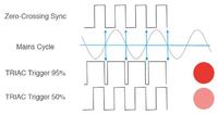
When triac is driven with 50%, the control pulse for the gate lasts 1 quadrant of the sinewave, that is 5ms. But triac theory says that if the gate is triggered with a minimum gate current provided by the datasheet, then it latches for the rest of the half period. So what is the need to drive the gate until next zero cross? A gate triggering duration in the order of microseconds shouldn't be enough?
 

FvM said:
No idea why you consider a flyback converter as inductive load?
Hi FvM. That confused me to be honest. Would you be so kind and point out (from load's point of view) what kind of triac do I need? I was searching for triacs with good performance for inductive load. Also the gate drive circuitry with MOC3023, was chosen for inductive load as well.
 

Alexxx,

The Offline switcher input impedance will be a capacitive (short circuit) when diodes are conducting until charged up then high impedance with Diodes off.

This leads to great instability with a tiny offline switcher.

You might want to rethink your approach and state your actual requirements.
 
  • Like
Reactions: alexxx

    alexxx

    Points: 2
    Helpful Answer Positive Rating
You might want to rethink your approach and state your actual requirements.
The requirements are already stated. Offline switcher as load, power<20W, I wish to drive it with 230V or 150V. The approach is to use a triac. What do you mean by "rethink"? Like using a transformer? The drive circuit I came up with, can be seen below. Do you have any comments on that schematic? Varistor will not be used for the time beeing.


I mean rethink the entire approach.

The offline switcher operates presumably somewhere in the 20kHZ to 1MHz range.
That means the energy storage time is < 1ms.

Meanwhile when you are trying to preregulate the input voltage where if the voltage demand exists early in the sinewave, it will remain only for the rest of the cycle regardless of load variation.
It wont work

THe offline switcher must be capable of the full range from 90 to 240 by design or not at all.

The problem is the energy storage time is not enough for triac method of control .
 
  • Like
Reactions: alexxx

    alexxx

    Points: 2
    Helpful Answer Positive Rating
The requirements are already stated. Offline switcher as load, power<20W, I wish to drive it with 230V or 150V. The approach is to use a triac.


The thing to remember on a SCR or TRIAC, is that they latch up via MT1 to MT2 current, not voltage.

Now, please see the attached file. The input current in a capacitor-input rectifier is as shown in the image...you can see that for several milliseconds after the voltage crosses zero, the current remains at zero.

rectifier waveform.jpg

Therefore, your trigger should extend long enough for the MT1 to MT2 current to rise above the minimum latching current.
Which, for the TRIAC you selected, can be as high as 60 mA.

Now, and this is important. I'm assuming that for your application, you require to only fully turn on or off the switcher. As skinnyguy mentions, you cannot regulate the input voltage via phase control in this application. A flyback is versatile enough to operate from 85 to 260 VAC without any additional input components.
 
  • Like
Reactions: alexxx

    alexxx

    Points: 2
    Helpful Answer Positive Rating
Now, and this is important. I'm assuming that for your application, you require to only fully turn on or off the switcher. As skinnyguy mentions, you cannot regulate the input voltage via phase control in this application. A flyback is versatile enough to operate from 85 to 260 VAC without any additional input components.

Better say, can't "regulate" the input voltage easily. I must confess that I assumed on/off-switching as design purpose. Now I found a kind of side-remark in post #6:
"MCU" reads mains voltage coming from the TRIAC and it takes appropriate decisions based on that voltage. This is why I need to output 230V or 150V AC from the TRIAC.

Obviously a phase angle controlled triac switch can't output "150 VAC" when the input voltage is 230 VAC. At best it can output a waveform that has either a RMS value or a peak value corresponding to 150 VAC. For a SMPS with rectifier and filter capacitor, mainly the peak voltage matters. Triggering the triac at about 130° might work.
 
  • Like
Reactions: alexxx

    alexxx

    Points: 2
    Helpful Answer Positive Rating
schmitt trigger said:
Therefore, your trigger should extend long enough for the MT1 to MT2 current to rise above the minimum latching current.
I chose a drive method as shown in post #8. Just leave the gate triggered, until zero cross interrupt comes. I suppose this is the best "long enough" I can get.

FvM said:
Now I found a kind of side-remark in post #6:
Yes, that's exactly what I meant. I am not trying to regulate the voltage on the secondary. This will be 24V in any case! This DC is used to supply 120 LEDs. The MCU on the secondary reads mains voltage and will proceed to the dimming of the LEDs, based on the measurement from mains. I tried that with a variac and worked OK. With a TRIAC small test board also worked OK (the "third-party" dimmer board), but the TRIAC burned a couple of times, so I'm redesigning.

FvM said:
Triggering the triac at about 130° might work.
You mean conductance angle 130°? Start triggering at 60° and 240°?
 

No I meant 50° conductance angle, or may be less. Any trigger before or at the peak voltage ill result in full peak voltage. But the operation also depends on the kind of switched mode controller.
 

I chose a drive method as shown in post #8. Just leave the gate triggered, until zero cross interrupt comes. I suppose this is the best "long enough" I can get.


Yes, that's exactly what I meant. I am not trying to regulate the voltage on the secondary. This will be 24V in any case! This DC is used to supply 120 LEDs. The MCU on the secondary reads mains voltage and will proceed to the dimming of the LEDs, based on the measurement from mains. I tried that with a variac and worked OK. With a TRIAC small test board also worked OK (the "third-party" dimmer board), but the TRIAC burned a couple of times, so I'm redesigning.


Ok, from your statement above, "The MCU on the secondary reads mains voltage and will proceed to the dimming of the LEDs", you want to design a Triac dimmable offline LED driver. Is that assumption correct? If so, disregard everything else that I've written earlier.

Stating this fact on the very first post, would have allowed us to help you faster and avoid guessing your requirements.

If indeed you want to design a Triac dimmable offline LED driver, I would suggest that you study the datasheets and app notes for ICs that perform that function. For instance the LM3445.
 

Status
Not open for further replies.

Similar threads

Part and Inventory Search

Welcome to EDABoard.com

Sponsor

Back
Top