Continue to Site

Welcome to EDAboard.com

Welcome to our site! EDAboard.com is an international Electronics Discussion Forum focused on EDA software, circuits, schematics, books, theory, papers, asic, pld, 8051, DSP, Network, RF, Analog Design, PCB, Service Manuals... and a whole lot more! To participate you need to register. Registration is free. Click here to register now.

Suggestions for filtering the Noise from the circuit output

Status
Not open for further replies.
Looking at the waveforms in post #19, it seems to me that you are complaining on a high level. They really don't look bad, there are level variations expectable by the nature of the measurement, but no strong interferences, e.g. hum. A more effective low-pass or bandpass filter can further reduce spurious signals.

Regarding hum, we can expect that AC light sources produce 100 Hz hum (also an unsufficiently filtered power supply) while picked-up mains voltage should be 50 Hz, well distinguishable. AC light interferences also vanish when you turn out the light...
 

@Audioguru:Thankyou so far for explaining so many things.
Can you please explain some advantages of sallenkey lowpass filter over the Embedded Lab first stage filtering.
Thankyou.
 

A Sallen-Key filter can have 2 RC or 3 RC poles so it can filter 2 times or 3 times better than a simple single pole RC.
A Sallen-Key filter is not simply 2 RC or 3 RC poles that interact and produce a droopy response. The opamp isolates the RC poles and adds positive feedback at the corner frequency so the response is flat (not droopy) up to the corner then a sharp drop (not a gradual drop) past the corner.
 
Hello everyone,
I am planning to implement a notch filter for filtering the AC mains hum.Is it a good idea to implement the notch filter.
What are the considerations to be taken for the implementation and if possible can you a provide a design for the implementation.
Thanks.
 

Why do you have mains hum? Are unshielded wires picking up the interference? Is the photo-diode picking up AC light fluctuations?
Both problems have harmonics that a notch filter will not remove.
 

@FvM:"a low-pass is much better suited and doesn't need frequency fine tuning."
Yes,I did used a LPfilter as shown in this multisim simulation **broken link removed**and the here **broken link removed**
is the input and output of the simulated design where the green signal represents the Phototransistor output containing a DC value of 2.7v(the phototransistor analog output is acquired using labview and is dumped into the multisim) and the Orange represents the ouput from the LPfilter stage swinging at 1.2V around and the output of the LPfilter with the implementation of simulated circuit on breadboard is different as shown in the post1 Image of this thread .
From the output images it can be analysed that both the simulated and breadboard implementation is containing high frequency components. Does this mean the LPfilter is not doing the job perfectly?

@Audioguru:Is the photo-diode picking up AC light fluctuations?
I think so and I'm not sure because according to the NJR5501R datasheet shows they are placed in a Light Sealed Dark Box.Does this dark box mean that it wont pickup the AC mains from the light fluctuations.
Are unshielded wires picking up the interference?
I didn't understood this clearly.
Thanks.
 

Attachments

  • 8508.NJL5501R_E_20130418.pdf
    256 KB · Views: 45

I did used a LPfilter as shown in this multisim simulation .....
Why are you using a circuit that needs an opamp but instead you are using a Transimpedance Amplifier??

Does this mean the LPfilter is not doing the job perfectly?
since your circuit uses the WRONG kind of amplifier then it is not a lowpass filter.

@Audioguru:Is the photo-diode picking up AC light fluctuations?
I think so and I'm not sure because according to the NJR5501R datasheet shows they are placed in a Light Sealed Dark Box.Does this dark box mean that it wont pickup the AC mains from the light fluctuations.
Make the circuit with proper opamps and try it. I don't know if you built the circuit on a breadboard where the many rows of contacts and many wires all over the place pickup mains hum or if you are simulating it. I don't know if you are using a light box.

"Are unshielded wires picking up the interference?"
I didn't understood this clearly.
The connecting wires must be shielded (audio cables) to prevent interference from mains hum and radio transmissions.
 

@Audioguru:About the noise details
I implemented the circuit upto the phototransistor(TCRT) part(as shown in the embeeded blog but removed the 2N3904 and made the 150ohm connection directly to the LED)on breadboard with input supply at 3Vand got the output response of phototransistor as shown in the attached.The phototransistor collector itself picking up the noise I guess and this noise was carried all the way to the output of the LP filter as shown in the link1 of post27 in this thread and even filtering stage was unable to filter out this noise.
Can you suggest how to overcome this noise or remove as it will be very tough to simulate the output as the real output of PT itself will be low and this noise addition makes it unfigured.
Thanks.
 

Attachments

  • Output_Signal.pdf
    625.2 KB · Views: 67
Last edited:

I cannot see most of the settings on your oscilloscope.

I suspect that the rows of contacts on your breadboard and the many wires all over the place on your breadboard are antennas that are picking up mains hum.
For low frequency high sensitivity circuits you cannot use a breadboard, instead you need a compact pcb design and maybe have the circuit installed in a metal box connected to 0V.

The lowpass and highpass filters are extremely simple and their frequencies are so close together that the bandpass peak is very broad and is attenuated.
 
@Audioguru:Sorry,I forgot to mention that the images shown are in Labview by acquiring the signal form breadboard and not on the Oscilloscope.
Ok,then I will implement the phototransitor on the pcb board with the SallenkeyLP filter later.
As of now I will try to implement the Pulse detector using the photodiode and OPA381TAI.For this,I implemented the circuit as shown in figure6(b) of page12 in the datasheet of OPa381 with bias voltage of(+IN)=0.6,Rf=50K,Cf=47Pf and got the following output pulse as shown here **broken link removed**.
I also tried imeplementing the lowpass filter with 100nF and 560K making fc=2.8Hz as shown in the figure6(c) of the Opa381 datasheet but there was no improvement in the output was.
I calculated the feedback pole using formla(1) in page 11 with Rf=50K,Cf=47Pf and got feedback pole as 67KHz.Gain from formula(2) using Rf,Cf,GBW=18MHz resulting bandwidth=34Khz.
But I am confused with the calculations for Rf,Cf,gain and bandwidth limit for the obtained output singal of 100mV.The needed freq range of the output is 0.5Hz to 3Hz with the output signal being amplified upto a value of 2.5V as the max readable by the microcontroller is 3V.
And how to design a low frequency bandpass filter for the above.(as you mentioned in post12)
Can you please help me out with the above for the circuit design.
 

Page 12 of the datasheet for the OPA381 does not have a schematic. Why don't you post the schematic you used when you reply here?

The photo of your 'scope does not show its timebase setting so I do not know the frequency of the hum that is shown. The vertical setting is too small to see the waveform.

You forgot to tell us what is the input light to the photodiode.

The circuits on the datasheet are for very high frequency signals. Your heartbeat signals are at very low frequencies.
A 50k resistor with a tiny 47pF capacitor has a cutoff frequency of 67kHz which is much much higher than you want. If the 47pF is 470nF (0.47uF) then the cutoff frequency will be 6.7Hz. if the capacitor is 1uf then the cutoff frequency is about 3.4Hz which is what you want but it is a very simple filter with a shallow slope. Use a film capacitor that is 5%. Since your filters are very simple then they overlap and the bandwidth is very wide with reduced gain.
 

Last edited:

If the timebase of your 'scope was 1 second per division then the waveform wiggles are probably a heartbeat at about 75 beats per minute, not mains hum.
It is not sensitive enough.
You forgot to post your entire schematic so I am just guessing what you are doing.

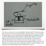
Are you making the IR LED and IR photodiode like this with the finger on top of both?
 

Attachments

  • heartbeat monitor.png
    heartbeat monitor.png
    269.1 KB · Views: 53

@Audioguru:Sorry I havent attached the design because I was implementing it on the board directly.Yes,you are right I am doing the same as shown in the attached design(I just made it now).
design.jpg
 
Last edited:

Some horizontal lines on your schematic are very faint and cannot be seen, maybe because the background is dark grey instead of white.
You do not show the part number of the opamp and it might be one that does not work with its inputs and output as low as 0.6V.
You do not show the supply voltage for your opamp.
You have the very simple lowpass filter with a cutoff frequency very high at 67kHz. It should be at 3.4Hz.

I am glad to see that the photodiode has the correct polarity.
 

@Audioguru:Hi ,the OPAMP is OPA381 with a provided supply voltage of 3V(the page1 of OPAMP datasheet states the supply range as 2.7 to 5.5V) and bias of 0.6V.
yes,I will change the combination to to get 3.4Hz.
Thanks.
 

The OPA381 is NOT an opamp. Instead it is a transimpedance amplifier.
Since your supply is only +3V then its output will be maximum about +2.5V when light on the photo-diode is very bright and will be +0.6V when it is dark.
The output waveform will not be the AC of a heartbeat, instead it will produce only the positive-going pulse.
 

Can you suggest me a way to improve the circuit design to get a AC waveform of the pulse instead of the positive pulse.Can't I use the TIA.
Thanks.
 
Last edited:

Status
Not open for further replies.

Part and Inventory Search

Welcome to EDABoard.com

Sponsor

Back
Top