mnvelocitypilot
Junior Member level 1
Hi team - I've been over in the electronic elementary questions forum trying to get some ideas on a problem I'm having where a homebrewed strobing 5A LED power supply keeps frying.
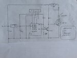
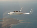
This is an LED strobe system I designed for use in my experimental aircraft. It's working fine in one application - as used to control a homebrewed LED landing light (which I can set to flash for better air to air anticollision lighting), but fails when applied to drive wingtip mounted LED strobes.
Here's the thread I've had running... several folks have made suggestions, but nothing is working:
https://www.edaboard.com/threads/319335/
To net this out - I designed two cards... a controller card, containing a PIC controller, the L78L05 regulator that drives the controller, and a 2N2222 transistor to uplevel the strobing output of the PIC to a higher voltage (to drive the mosfet switches).
The second card (which I call the power card), contains a LM338 used as a current limiter (set to 5A), and the mosfet (IRF510) used to strobe the Cree LEDs. The only difference between the nose mounted landing light system and the wingtip strobe system is that in the wingtip system I'm using one controller card to drive two separate power cards (one for each wingtip strobe).
The wingtip system works fine on the bench, but as installed in the aircraft, it immediately fails - the L78L05 regulator fries (shorts), which takes out the PIC controller. It's dead immediately after hitting the switch.
My theory has been that I'm getting a big reverse voltage spike in the aircraft installed system due to the approx. 14 feet of wire between the controller card + power card "power supply", and the LED. I've tried putting a protection diode (IN4005) across the LED line at the power supply end, and also using a IN918 across the L78L05 voltage regulator. It still fries.
The wire running to the LED is high quality belden, 3 conductor in a shielded wire.
I covered the specifics of the controller and power cards in an instructable:
https://www.instructables.com/howto/mnvelocitypilot/
I'd sure appreciate any ideas on how to make this work... very frustrating!
Thanks!

