natnoraa
Full Member level 1

- Joined
- Jun 19, 2011
- Messages
- 98
- Helped
- 12
- Reputation
- 24
- Reaction score
- 11
- Trophy points
- 1,288
- Activity points
- 2,108
Hi,
I have designed a multi-layer quadrature hybrid coupler(can be offset) in HFSS and assigned 4 ports to it as shown:

Port 1: input
Port 2: transmitted
Port 3: coupled
Port 4: isolated
Step 1: I designed each layer to be a quarter wavelength at the frequency of my interest. Such that Length_1 (top metal layer) = X um. Length_2 (the next metal layer) = Y um
Step 2: Simulate the 4 ports and then port the s4p file to ADS for simulation
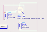
Step 3: Connection is as seen:

Questions:
1) Why can't i connect 1&4, 2&3 in a differential way? (results will be very wrong with k value more than 1). Because usually you'll see port 1,4 on the left side and port 2,3 on the right side (Edit: this is a stupid comment to give am sorry. Could it be because ports 1 and 2 are on the same layer and vice versa for 3 and 4?)
2) Upon configuring as shown, I can use the Z parameters to obtain the Zeven and Zodd to get the values that I want?
3) In HFSS, i should trial and error W1 and W2 for the respective metals and the offset (the overlap length from the cross sectional view) to give me the broadband 90 degree that I want at the range of frequency of my interest?
Any help would be appreciated or even pointing out what I've done wrongly here. Thanks!
Natnoraa
I have designed a multi-layer quadrature hybrid coupler(can be offset) in HFSS and assigned 4 ports to it as shown:

Port 1: input
Port 2: transmitted
Port 3: coupled
Port 4: isolated
Step 1: I designed each layer to be a quarter wavelength at the frequency of my interest. Such that Length_1 (top metal layer) = X um. Length_2 (the next metal layer) = Y um
Step 2: Simulate the 4 ports and then port the s4p file to ADS for simulation
Step 3: Connection is as seen:

Questions:
1) Why can't i connect 1&4, 2&3 in a differential way? (results will be very wrong with k value more than 1). Because usually you'll see port 1,4 on the left side and port 2,3 on the right side (Edit: this is a stupid comment to give am sorry. Could it be because ports 1 and 2 are on the same layer and vice versa for 3 and 4?)
2) Upon configuring as shown, I can use the Z parameters to obtain the Zeven and Zodd to get the values that I want?
3) In HFSS, i should trial and error W1 and W2 for the respective metals and the offset (the overlap length from the cross sectional view) to give me the broadband 90 degree that I want at the range of frequency of my interest?
Any help would be appreciated or even pointing out what I've done wrongly here. Thanks!
Natnoraa
Last edited: