Continue to Site

Welcome to EDAboard.com

Welcome to our site! EDAboard.com is an international Electronics Discussion Forum focused on EDA software, circuits, schematics, books, theory, papers, asic, pld, 8051, DSP, Network, RF, Analog Design, PCB, Service Manuals... and a whole lot more! To participate you need to register. Registration is free. Click here to register now.

Stepper Motor speed Control

Status
Not open for further replies.

vish2207

Newbie level 5
Joined
Jan 28, 2014
Messages
10
Helped
0
Reputation
0
Reaction score
0
Trophy points
1
Activity points
103
Hi Everyone,

My project is to make a Bipolar stepper motor drive using discrete components. I have NEMA 34 86mm 4A 1.8degree stepper motor as a load. I have made drive using two full H bridge which uses IRF540(N Mosfet) and IRF9540(P Mosfet). I am driving these Mosfets using discrete transistors BC547. After few tweaking in the gate drive circuit, now MOSFETs are driven correctly.

I am driving the Motor in the Full step mode which has following waveforms.

BipolarSteppers.jpg


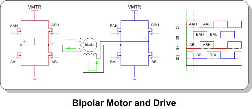
In my case, the time for one step which is shown by two dotted green lines in the waveforms, is kept 1850uS. This time has been decided by lot of iteration of different timings. This creates minimum vibration in the motor and optimum current consumption. Now at this stage the RPM of the motor is around 160. Theorically it is 162.

I want to increase Motor RPM to around 300. If I reduce the step time from 1850uS to 900uS, the motor stalls. What should I do to fix this?

I tried to run the same motor with another small off the shelf drive which is using TB6560 IC from TOSHIBA. If I drive it in full step mode, it gives some where around 300 RPM for the same motor without considerable vibration and limited current.

Thanks in advance,
Vishal Prajapati
 

Hi vish2207, to overcome this problem you should use a linear speed profile, where the step rate should be incremented linearly using constant acceleration. This is not the only way to do that, but is the most common. Search using Google for Linear Speed Profile for stepper motors and you'll find some works, using AVR, PIC and others.

I've trying to do something like this but to control 3 stepper motors at once. If you can find something (for PIC18) I would like you tell me about it. Yosmany325.
 

Because of the inductive nature of the motor windings they should be driven from a constant current source, their time constant is L/R, so try putting resistance in series with the windings to reduce the time constant , so the current rises faster and perhaps it will cure the problem. You will need to increase the voltage to compensate.
Frank
 

Hi vish2207, to overcome this problem you should use a linear speed profile, where the step rate should be incremented linearly using constant acceleration. This is not the only way to do that, but is the most common. Search using Google for Linear Speed Profile for stepper motors and you'll find some works, using AVR, PIC and others.

Thanks a lot Yosmany325. Your trick worked. Now I am able to run the motor till 288 RPM instead of 162 earlier. I have tried to give linear acceleration but does not work properly. It skips the intermediate steps and gets locked in between revolution as if it is skiping intermediate steps. So I am not giving exact linear acceleration but with trial and error of different timings try to smooth the steps.

I still needs higher speed. So, if try to reduce the step time below 1050uS, it again starts skeeping steps. I think I should go for half step sequence and then try to decrease the step time to increase speed beyond 288 RPM.

What if I want to reduce the speed during run time? I am thinking of reduce the step on time and lock the motor before next step so lock time will become off time of motor. Is this the right approach to decrease speed of motor?
 

The way to slow down the stepper speed is the same used to increase it. Did you see an application note of AVR or others. Search for SLYT482 (from Texas Instruments), avr466, etc.
 

As chuckey said, stepper motors are best used with current source drivers. It doesn't need to be complex, you just need a peak current mode control loop on each half bridge.
 

Using a constant current approach give the possibility of reach greater speeds, but also you must start slow and then increase speed and to stop motor you must slow down speed and then stop. Consult your motor datasheet, in the graph of speed/torque characteristics look for pull in/pull out torque and max start/stop speeds. You should learn some basic concepts of stepper motors if you like to do something serious. Yosmany325.
 

I am using 24V supply to H bridge. I have tried Half step sequence and linear acceleration profile be which I get 428 RPM now but with almost zero torque.

So, I think if I want to go faster, I need to provide PWM in sine and cosine pattern to all the lower MOSFETs of both H Bridge to make it a micro stepping drive which I think will compensate for torque better.

By the way I also asked if I want to decrease the speed of motor which is correct method for it?

Opt 1: Increasing delay between two step sequences which increases current and consequently torque?

Opt 2: I should provide One step sequence for x time and then lock the motor for y time. After x + y time, I provide second step sequence for another x time and wait for y time.

Opt 3: I should keep the time according to max speed and use reduced PWM duty cycle to decrease current there by reducing speed?

Note: I am right now not using any PWM inputs to H bridges. I will need to change the MCU for that.
 

vish2207, I would suggest you to use a specialized driver for your motor, you will gain in many aspects:

1- All hardware control will be automatic, i.e. constant current, microstepping (if the driver contains it).
2- Ease of use, i.e. only need 3 signals, Enable, Step and Direction.

There are too many choices, I know one of Allegro, A3977, with a maximum current of 2.5A at 35V. I hope this help you.
 

Note: I am right now not using any PWM inputs to H bridges. I will need to change the MCU for that.
PWM is basically mandatory for BDC drives. No wonder you're having trouble.
 

Status
Not open for further replies.

Similar threads

Part and Inventory Search

Welcome to EDABoard.com

Sponsor

Back
Top