Welcome to our site! EDAboard.com is an international Electronics Discussion Forum focused on EDA software, circuits, schematics, books, theory, papers, asic, pld, 8051, DSP, Network, RF, Analog Design, PCB, Service Manuals... and a whole lot more! To participate you need to register. Registration is free. Click here to register now.
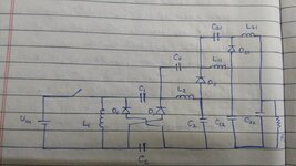
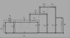
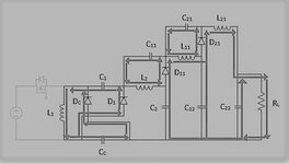
Can someone help me with the steady state analysis of this DC-DC converter? I want to propose an equation for the voltage conversion ratio of this converter in terms of the duty cycle.
As you might know, the first step is to build the state matrices A, B, C, D, which is missing from your post. By the way, it would be recommended that you adopt the standard symbology in circuit design, in which connecting lines have a 'dot' symbol indicating that are on the same net. Anyway, the fact that there is a diode in the circuit, this lead to assumption that would behave as non-linear, and the methodology perhaps is a little different, anyway, the basics showing what you have done so far is missing, as said.
Voltage multipliers (most of them) make use of one or more charge pump capacitors. The cap charges in one direction through a diode during one half of the cycle, then discharges through a different diode during the other half of the cycle.
Your circuit has more than one stage. With light load there is a maximum output voltage it can reach. As you increase load, it draws more current, forcing the circuit to draw increased current in turn.
The overall effect is to cause output voltage to droop. If your capacitors have high enough Farad value they tend to hold their charge voltage, whereas meager cap values go through voltage swings, with the result that output voltage droops even more.
I guess your experiments shall look at the part played by switching frequency and duty cycle.
This site uses cookies to help personalise content, tailor your experience and to keep you logged in if you register.
By continuing to use this site, you are consenting to our use of cookies.