MZulkarnain Jaranee
Newbie level 5

- Joined
- Nov 27, 2014
- Messages
- 8
- Helped
- 0
- Reputation
- 0
- Reaction score
- 0
- Trophy points
- 1
- Activity points
- 70
Hi Everyone,
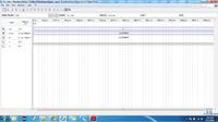
I'm making an asynchronous pipeline which mean every stage of pipeline control by local controller, using Quartus 2, written in VHDL language. The problem i'm facing is unversity waveform program shown that the data is not transferred between stages as shown in below images. Below image is simulated from two stages pipeline. The function of the pipeline is FIFO.

D_out is the final output from the pipeline meanwhile, D is the output from stage 1 and is the input for stage 2.
after many attempts to fix, somehow I can figure out what is the problem.
Hopefully, anyone here can help/advice me.
Fyi, there is two state only in this pipeline.
State0 - transfer data between stages when stage1 is full and stage2 is empty
State1 - disable data transfer between stages when stage 2 is full and stage 1 is empty.
The state machine is written in the state_conductor.vhd file.
Here is the code
------------- top entity ---------------------------
------------- sub module -----
------------- gasp_ctrl.vhd ----- this module responsible to enable and disable the dflipflop in dfflop.vhd --------------
-------------- dfflop.vhd --- for store the data in stage
-----------------state_conductor.vhd----responsible either to transfer data between stage or no
---------------------------------------------------
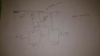
CIRCUIT IMAGE

I'm making an asynchronous pipeline which mean every stage of pipeline control by local controller, using Quartus 2, written in VHDL language. The problem i'm facing is unversity waveform program shown that the data is not transferred between stages as shown in below images. Below image is simulated from two stages pipeline. The function of the pipeline is FIFO.

D_out is the final output from the pipeline meanwhile, D is the output from stage 1 and is the input for stage 2.
after many attempts to fix, somehow I can figure out what is the problem.
Hopefully, anyone here can help/advice me.
Fyi, there is two state only in this pipeline.
State0 - transfer data between stages when stage1 is full and stage2 is empty
State1 - disable data transfer between stages when stage 2 is full and stage 1 is empty.
The state machine is written in the state_conductor.vhd file.
Here is the code
------------- top entity ---------------------------
Code:
library ieee;
use ieee.std_logic_1164.all;
use IEEE.STD_LOGIC_UNSIGNED.ALL;
use IEEE.STD_LOGIC_ARITH.ALL;
entity gasp is
port(
	x, y : in std_LOGIC;
	d_in : in integer;
	d_out, d: out integer
);
end gasp;

architecture gasp of gasp is
COMPONENT dfflop
		port(
			data_in:	in integer;
			enable:		in std_logic;
			data_out:	out integer
		);
END COMPONENT;
COMPONENT gasp_ctrl
	PORT
	(
		in0, in1 : in STD_LOGIC;
		en : out STD_LOGIC
	);
END COMPONENT;
COMPONENT state_conductor
      port(

		in_left : in std_logic; -- - in_left is left bit for current_state
		in_right : in std_logic; -- - in_right is right bit for current_state
		state : out std_logic -- assert low or high bit for gasp controller
		);
END COMPONENT;
	---- state conductor wire ------
	signal state_1: std_LOGIC;
	------- enable wire ------------
	signal en_1, w, en_2, z: std_LOGIC ;
	------- data wire ------------
	signal data_wire, data_wire1 : integer ;
	begin

		------------ stage 1 ---------------------
		ctrl_1 : gasp_ctrl port map (in0 => x, in1 => state_1, en => en_1);
		latch_1 : dfflop port map (data_in => d_in, enable => en_1, data_out => data_wire);
		conductor_1 : state_conductor port map (in_left => en_1 ,in_right => en_2, state => state_1);
		ctrl_2 : gasp_ctrl port map (in0 => state_1, in1 => y, en => en_2);
		latch_2 : dfflop port map (data_in => data_wire, enable => en_2, data_out => d_out);
		d <= data_wire;

end gasp;
------------- sub module -----
------------- gasp_ctrl.vhd ----- this module responsible to enable and disable the dflipflop in dfflop.vhd --------------
Code:
library ieee;
use ieee.std_logic_1164.all;
use IEEE.STD_LOGIC_UNSIGNED.ALL;
use IEEE.STD_LOGIC_ARITH.ALL;


ENTITY gasp_ctrl IS
	PORT
	(
		in0, in1 : in STD_LOGIC;
		en : out STD_LOGIC

	);
END gasp_ctrl;

ARCHITECTURE structure OF gasp_ctrl IS


BEGIN
    en <= (NOT in0) AND in1;
END structure;
-------------- dfflop.vhd --- for store the data in stage
Code:
---------------------------------------------
library ieee;
use ieee.std_logic_1164.all;
use IEEE.STD_LOGIC_UNSIGNED.ALL;
use IEEE.STD_LOGIC_ARITH.ALL;

---------------------------------------------

entity dfflop is
port(
	data_in:	in integer;
	enable:		in std_logic;
	data_out:	out integer
);
end dfflop;

----------------------------------------------

architecture behv of dfflop is
begin

   process(enable)
   begin
   -- enable rising edge ----
	if (rising_edge(enable)) then
	    data_out <= data_in;
	end if;

   end process;

end behv;
Code:
library ieee;
use ieee.std_logic_1164.all;
use IEEE.STD_LOGIC_UNSIGNED.ALL;
use IEEE.STD_LOGIC_ARITH.ALL;

LIBRARY work;

ENTITY state_conductor IS
	PORT
	(
		in_left : in std_logic; -- - in_left is left bit for current_state
		in_right : in std_logic; -- - in_right is right bit for current_state
		state : out std_logic -- assert low or high bit for gasp controller

	);
END state_conductor;

ARCHITECTURE structure OF state_conductor IS
	type STATE_TYPE is (S0, S1);
   signal CURRENT_STATE: STATE_TYPE ;
	signal NEXT_STATE: STATE_TYPE := S1;
	signal full_empty : std_logic_vector(1 downto 0) ;
	signal en : std_logic;
BEGIN


	 full_empty(1) <= in_left;
	 full_empty(0) <= in_right;
	 CURRENT_STATE <= NEXT_STATE after 7ns;
	 process(CURRENT_STATE, full_empty)
	  begin
		 case CURRENT_STATE is
			 when S0 => state <= '0';
				if full_empty = "10" then NEXT_STATE <= S1;
				else NEXT_STATE <= S0;
			 end if;
			 when S1 => state <= '1';
				if full_empty = "01" then NEXT_STATE <= S0;
			 else NEXT_STATE <= S1;
			 end if;
		end case;
	 end process;


END structure;CIRCUIT IMAGE


