Continue to Site

Welcome to EDAboard.com

Welcome to our site! EDAboard.com is an international Electronics Discussion Forum focused on EDA software, circuits, schematics, books, theory, papers, asic, pld, 8051, DSP, Network, RF, Analog Design, PCB, Service Manuals... and a whole lot more! To participate you need to register. Registration is free. Click here to register now.

start up in current source

Status
Not open for further replies.

mostafah67

Member level 1
Member level 1
Joined
Jun 2, 2013
Messages
39
Helped
0
Reputation
0
Reaction score
0
Trophy points
1,286
Visit site
Activity points
1,575
there is a current source here which is independent to supply voltage and it have a start up circuit (M5) that prevents zero current in the loop:

startup.JPG

(figure from:analog cmos integrated circuit by: behzad razavi)

i simulate the circuit but M5 is cutoff, i think i choose the wrong value for Rs. can you help me that what is the start up condition in this circuit:shock:
 

I think that in work mode, M5 must be in cutoff mode and no current flows through it, and you must choose value of Rs only for wanted current value (equation 11.4)
 
thanks, before turning of M5 it is on for a specific time, do am right? is it specific condition to work the start up transistor correctly? and is it possible this transistor don't work correctly so that the circuit current was other than thats equation 11.4 was predicted?

1.JPG
 

thanks, before turning of M5 it is on for a specific time, do am right?

Yes, you are right.

is it specific condition to work the start up transistor correctly?

Yes, drain-source of diode must be larger Vth :)

and is it possible this transistor don't work correctly so that the circuit current was other than thats equation 11.4 was predicted?
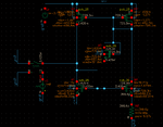
Yes, value of resistor may be very big or vdd very small and transistors works not in saturation. Here my example circuit:
sch_startup.png
There is zero volt on drain of M1 for 10 us.
And current waveforms for startup wit diode and without diode:
waveform_startup.png

Without diode start time more than twice.
 
thanks a lot, can you give me the value of R and Vdd, and the ratio of Mos??
another question which i have, what is the switch in the right side of circuit? i didn't see it before in the similar circuits, is it necessary to circuit work correctly?
 
Last edited:

thanks a lot, can you give me the value of R and Vdd, and the ratio of Mos??
another question which i have, what is the switch in the right side of circuit? i didn't see it before in the similar circuits, is it necessary to circuit work correctly?

If i remember correct W/Ln = 36, W/Lp = 56, R = 10 Ohm, Vdd = 2V.

I just make zero current as initial with that switch. You can delete it without any troubles.
 
Status
Not open for further replies.

Part and Inventory Search

Welcome to EDABoard.com

Sponsor

Back
Top