Continue to Site

Welcome to EDAboard.com

Welcome to our site! EDAboard.com is an international Electronics Discussion Forum focused on EDA software, circuits, schematics, books, theory, papers, asic, pld, 8051, DSP, Network, RF, Analog Design, PCB, Service Manuals... and a whole lot more! To participate you need to register. Registration is free. Click here to register now.

Standalone miniature Monopole or Dipole antenna. How to know what is what?

Status
Not open for further replies.

guliveron

Newbie level 4
Newbie level 4
Joined
Feb 25, 2014
Messages
5
Helped
0
Reputation
0
Reaction score
0
Trophy points
1
Visit site
Activity points
36
Hello!
Maybe you could help. How to distinguish what is monopole and what is dipole antenna in case of miniature standalone examples like:
antenna.PNG

Ok, the part closer to the wire seems to be a ground. But why it is so small? Is it some kind of DGS structure?

Thanks.
 

No detail of the feeding part can be seen on the picture. My best guess is that the left long trace works like a monopole, while the right short conductor serves as the ground. This guess is made due to the apparent asymmetric structure.
 

Based on the point where entry cable is supposed connected, seems more as a asymetric dipole type with a reflector, however such categorization I believe that properly doesn´t matter, due this geometry results from a irradiation pattern matching for several carriers, becoming a complex structure.
 

It is a kind of asymmetric dipole with folded arms.
I think not even the designer of this antenna doesn't know exactly what it is. He just cut and paste in the simulator to get the best performances in specified bands.
The net, the antenna books, and the RF magazines, are full of examples of crazy shapes of printed antennas that takes a lot of time to understand what they are.
Of course, all of them have patent granted or pending.
 
Ok, it is an asymmetric dipole antenna. But then How it is possible to connect it to wireless modules with unbalanced inputs? Like here: modpic.PNG
I thought that it is possible for monopole antennas. Or an antenna has a balun structure somewhere?
 

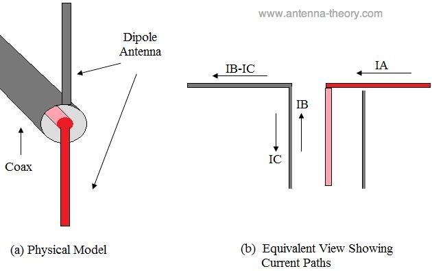
The problem is that the feed cable becomes part of the antenna, it's length and route influences the antenna impedance and directional characteristic.

To characterize the antenna on it's own, you can shove several ferrite tubes up the cable until the antenna entry point. On the other hand, the antenna will be rarely used without a transmitter board, so it makes possibly more sense to measure th eantenna characteric with the transmitter board in place.
 

Thank you!

So that's why it's possible to connect such kind of dipole antenna as well?
**broken link removed**

Then the grounded part of antenna and the cable will also participate in radiation if it is conntected to an unbalanced input like here?
balun.jpg

And therefore characteristics of the antenna will be damaged.

Please correct me if i'm not right.
 

Status
Not open for further replies.

Part and Inventory Search

Welcome to EDABoard.com

Sponsor

Back
Top