franticEB
Full Member level 3

- Joined
- May 10, 2010
- Messages
- 153
- Helped
- 1
- Reputation
- 2
- Reaction score
- 2
- Trophy points
- 1,298
- Activity points
- 2,551
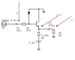
hello to everyone could you help me in the analysis of this circuit?

With a simulation I get the following results:
with a square wave in input 0-5Volts on the node indicated by the red arrow (1) there is the same wave but shifted by 2.5Volt below the 0 level.
The same occurs at the point indicated by the arrow number 2. There is a square wave 0-2V and at the point indicated by the arrow 3 there is a square wave -1V +1 V.
I do not understand this behavior
Why the node indicated by arrow n° 2 is 0-2V and not 0-2.5 V?
thanks

