Continue to Site

Welcome to EDAboard.com

Welcome to our site! EDAboard.com is an international Electronics Discussion Forum focused on EDA software, circuits, schematics, books, theory, papers, asic, pld, 8051, DSP, Network, RF, Analog Design, PCB, Service Manuals... and a whole lot more! To participate you need to register. Registration is free. Click here to register now.

Square law amplifier circuit needed

Status
Not open for further replies.

neazoi

Advanced Member level 6
Joined
Jan 5, 2008
Messages
4,122
Helped
13
Reputation
26
Reaction score
15
Trophy points
1,318
Location
Greece
Activity points
36,951
Hi,
I need a circuit for the opposite of the logarithmic amplifier. I.e. I need to amplify more the higher level signals and less the lower level signals.

In some spectrum analyzers this is caller a square law amplification.
I want the circuit to work in HF spectrum.
Could you suggest a way to do this (discrete components preferred).
--- Updated ---

Hi,
I need a circuit for the opposite of the logarithmic amplifier. I.e. I need to amplify more the higher level signals and less the lower level signals.

In some spectrum analyzers this is caller a square law amplification.
I want the circuit to work in HF spectrum.
Could you suggest a way to do this (discrete components preferred).
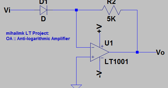
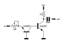
I just found that it is called an exponential amplifier. So I am looking a (preferably discrete) exponential amplifier for HF
 
Last edited:

A squelch circuit or something like it. Or an expander if the signal was audio.
A CdS photocell is used in some effects boxes. Send your signal to a peak detector. The output is DC. Light an LED with it. The brighter the LED, the less photocell resistance. It can divert more or less of your original signal.

Or feed the DC level as bias to a JFET, configured as a volume control for your original signal.

Or feed the DC level to bias a transistor, in order to shift its region of operation between high or low gain. This may require a lot of experimentation in order to get it right.
 

Unless I am reading something wrong, this is not what I was thinking.
The circuits I find are using a diode or a transistor at the input of an opamp.

I need such an amplifier, so that I can amplify strong noise pulses that present along with weaker
A squelch circuit or something like it. Or an expander if the signal was audio.
A CdS photocell is used in some effects boxes. Send your signal to a peak detector. The output is DC. Light an LED with it. The brighter the LED, the less photocell resistance. It can divert more or less of your original signal.

Or feed the DC level as bias to a JFET, configured as a volume control for your original signal.

Or feed the DC level to bias a transistor, in order to shift its region of operation between high or low gain. This may require a lot of experimentation in order to get it right.
Hm... I think it is not clear to me how this will work.
The idea is to attenuate the wanted weak signal plus the strong noise pulses present with it. Then use an exponential amplifier, so that the strong noise pulses amplified more than the weak wanted signal. That way you get even weaker signal and even stronger noise pulses than before.
I know it sounds weird, but my experiment requires thia behaviour
 

If I understand, this isn't a tone control but a way to make it easier to distinguish between impulse noise and background signal. I think the idea is that a weak signal will be amplified less than a strong one, the strong one being the interference. When the interference level is higher it can be more easily used to gate itself out of the weak signal or even just clipped off. Using the inverse amplification function then restores the weaker signal's linearity.

Brian.
 

    neazoi

    Points: 2
    Helpful Answer Positive Rating
If I understand, this isn't a tone control but a way to make it easier to distinguish between impulse noise and background signal. I think the idea is that a weak signal will be amplified less than a strong one, the strong one being the interference. When the interference level is higher it can be more easily used to gate itself out of the weak signal or even just clipped off. Using the inverse amplification function then restores the weaker signal's linearity.

Brian.
Exactly!
So I am looking of an exponential amplifier circuit for HF.
I have seen these opamp circuits that include just a diode in the input, but I am thinking that this diode will act as a rectifier on HF so it wont be good.
Any ideas?

Can it be that easy? The input diode replaced by a grounded base PNP like shown here https://bestengineeringprojects.com/antilogarithmic-amplifier-derivation/
followed by a simple transistor amplifier. The input pot sets the sensitivity.

I know I missing some bias for the NPN, but how should I apply it without disturbing the PNP?

Another idea is to have an LOG amplifier, followed by an inverter. Would this work as well?
 

Attachments

  • phase.JPG
    phase.JPG
    8.3 KB · Views: 76
Last edited:

I think you will be disappointed by the simple solution you show and how well it works would be very dependent on DC conditions and impedances. A log amplifier follwed by an inverter just gives you an inverted log signal, you need an exponential gain characteristic followed by a log amplifier to return to linearity.

Although the idea is good, it does rely on the interference being stronger than the wanted signal and it has two serious drawbacks:
1. It still cant tell what is wanted and unwanted signal, amplitude alone is not enough to distinguish them.
2. It has a very much reduced dynamic range. Instead of your signal path having to cope with wanted signals, it needs the extra headroom to handle the expanded version of it.

I would lean towards experimenting with amplitude tracking with two time constants, a slow one to follow the signal envelope and a fast one to pick out rapid changes. Although it could be fooled by an intentional rapid change in modulation, it would to a large degree detect impulse changes. With a little ingenuity, you could add a sample and hold circuit so the previous sampled level was held throughout the interference period. Aesthetically it would sound better than simply leaving gaps in the signal or clipping the amplitude.

Brian.
 

    neazoi

    Points: 2
    Helpful Answer Positive Rating
I think you will be disappointed by the simple solution you show and how well it works would be very dependent on DC conditions and impedances. A log amplifier follwed by an inverter just gives you an inverted log signal, you need an exponential gain characteristic followed by a log amplifier to return to linearity.

Although the idea is good, it does rely on the interference being stronger than the wanted signal and it has two serious drawbacks:
1. It still cant tell what is wanted and unwanted signal, amplitude alone is not enough to distinguish them.
2. It has a very much reduced dynamic range. Instead of your signal path having to cope with wanted signals, it needs the extra headroom to handle the expanded version of it.

I would lean towards experimenting with amplitude tracking with two time constants, a slow one to follow the signal envelope and a fast one to pick out rapid changes. Although it could be fooled by an intentional rapid change in modulation, it would to a large degree detect impulse changes. With a little ingenuity, you could add a sample and hold circuit so the previous sampled level was held throughout the interference period. Aesthetically it would sound better than simply leaving gaps in the signal or clipping the amplitude.

Brian.
My solution is not to leave gaps like a noise blanker does. My solution is to phase out the noise pulses and feed them back to the channel. This will not leave gaps it will only reduce the noise pulses. The problem of distinguishing noise pulses from noise is always difficult and it is there with any circuit really.
Circuits with phase cancellation (eg. xphaser) deal with this with a separate antenna of low gain, placed near the interference source. .

The solution I propose is for a single antenna. Attenuation of the signal and noise (local pulsating noise being higher than signal), then feed this signal to an exponential amplifier so as to increase the noise even more and not so much the signal. Then phasing out the pulses by a simple transistor inverter.

This solution does not require a second antenna, neither adjustable phasing control, neither input filters, as we care only in what happens in the bandwidth we hear, so we adjust the attenuation to cope with that noise. Because we are not cutting the signal but we rely on continuous phasing of all signals received by the phase inverter (at all bands), there is no risk of accidentally chopping out the wanted signal by interference caused outside of the band. So no input filters are needed.

I could try it without any exponential amplifier, but I thought that it might be better to have one there, to dig further into the signal and phase out noise, without reducing the signal much.

This solution is usable when the interference is so much that you cannot hear the signal. Interference lower than the signal is less important and can be handled sometimes by the RF gain.

Any ideas are helpful.
Ok is the attached circuit an exponential amplifier? It detects signals above a threshold and inverts their phase as well.
I am thinking that the noise pulses are symmetrical aren't they? So I would need also something for the negative side of the sine, to convert it to upwards going pulses.
 

Attachments

  • exponentialamp2.PNG
    exponentialamp2.PNG
    138.9 KB · Views: 89

It uses the non-linear characteristic of the transistor at low bias levels to produce the signal expansion but if you look carefully, all it does is use the transistor as an inverter and it only works at the point where signal level starts to make it conduct. Imagine a horizontal line at about +600mV and you will see the output is a mirror image of the input along that line. The problem is keeping the wanted signal just below 600mV at all times as anything above that would make the transistor conduct and be seen as interference.

I wouldn't rely on noise being symmetrical, the signal you are seeing is a composite of wanted signal and noise with both being a complex mix of amplitude and phase, the signal could be almost anything.

Brian.
 

    neazoi

    Points: 2
    Helpful Answer Positive Rating
It uses the non-linear characteristic of the transistor at low bias levels to produce the signal expansion but if you look carefully, all it does is use the transistor as an inverter and it only works at the point where signal level starts to make it conduct. Imagine a horizontal line at about +600mV and you will see the output is a mirror image of the input along that line. The problem is keeping the wanted signal just below 600mV at all times as anything above that would make the transistor conduct and be seen as interference.

Hm... I am actually going to have a control knob, so that the user can set the level of the input signal (plus noise pulses) and let the pulses only pass above the "knee" point of the transistor conduction.
The inverter is actually a benefit because I need to phase out the pulses at a later stage.

If I use a germanium transistor, I could possibly make the circuit more sensitive (around 200mv) I guess?


I wouldn't rely on noise being symmetrical, the signal you are seeing is a composite of wanted signal and noise with both being a complex mix of amplitude and phase, the signal could be almost anything.

Brian.

This one is not very clear. Souldn't I see noise spikes at both the positive and negative cycles of the sinewave?
Th inverter I have shown works only in the positive cycle (as far as I understand it). Or I am thinking it totally wrong, because the transistor will actually amplify RF but only when RF passes a certain knee point on both sides of the RF cycle. But the simulation does not show that.
 
Last edited:

Hm... I am actually going to have a control knob, so that the user can set the level of the input signal (plus noise pulses) and let the pulses only pass above the "knee" point of the transistor conduction.
The inverter is actually a benefit because I need to phase out the pulses at a later stage.

If I use a germanium transistor, I could possibly make the circuit more sensitive (around 200mv) I guess?


This one is not very clear. Souldn't I see noise spikes at both the positive and negative cycles of the sinewave?
Th inverter I have shown works only in the positive cycle (as far as I understand it). Or I am thinking it totally wrong, because the transistor will actually amplify RF but only when RF passes a certain knee point on both sides of the RF cycle. But the simulation does not show that.
Ok this is what I am talking about. (see attached).
Now it should respond to both positive and negative voltages of the AC.
The input voltage has to be varied to be between 0.35-0.4v by the user, to select the level.
I do not know if I am doing the wrong thing.
 

Attachments

  • exp.PNG
    exp.PNG
    38.9 KB · Views: 77

Status
Not open for further replies.

Part and Inventory Search

Welcome to EDABoard.com

Sponsor

Back
Top