Continue to Site

Welcome to EDAboard.com

Welcome to our site! EDAboard.com is an international Electronics Discussion Forum focused on EDA software, circuits, schematics, books, theory, papers, asic, pld, 8051, DSP, Network, RF, Analog Design, PCB, Service Manuals... and a whole lot more! To participate you need to register. Registration is free. Click here to register now.

SPI serial resistor?

Status
Not open for further replies.

ivenzar

Member level 2
Joined
May 28, 2015
Messages
46
Helped
3
Reputation
6
Reaction score
3
Trophy points
8
Activity points
361
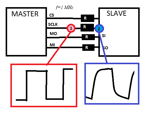
Given the situation depcited in Figure 1 operating at f=1MHz. There are some serial resistors. Which is the function of those resistors?
The waveform obtained in 1 is different from the one measured at 2 (seems a capacitor charging and discharging). Why?

Someone knows any page to find more information?

Greetings.

8498720800_1444820015.png
 
Last edited by a moderator:

What SPI clock speed are you using?
How long are the SPI lines?
What is the construction, traces, wires of the SPI connections?
What is the value of the resistor used over there?

- - - Updated - - -

If your traces are longer it is recommended to use these resistor and should be placed very nearer to driving source. At master side you need to put for CLK, MOSI & CLK lines and at the slave side you need to put for MISO line.

These resistors terminate the lines to reduce or eliminate undershoot and overshoot at the receiving end. Care must be taken with multiple SPI slaves though, series terminating is best with point to point connections.
 

Hi,

I use / used tht resistor because:

1) to avoid short circuit. Here especially at MISO lines. Usually only one slave is active at a time, but in case the CS os SS lines are generated in a PLD this could give problems when the PLD is not programmed.
Sometimes the SPI lines have double function (like AVR microcontrollers) where the AVR can act as a SPI master, but the AVR can be programmed with the same lines (AVR as slave).
Then you need the resistors also at the other lines.

2) on very sensitive ADCs or DACs. Here the resistors give a known impedancefor the datasignals and thus reducec current peaks caused by the edges of the SPI signals. This avoids noise.
This is discussed on "Burr Brown --> now TI application notes" for high resolution ADCs.

You see the edgeas are defored after the resistor. This is true, but should (or do I say "must") not harm the data transfer.
The resistors should be placed next to the slave. then the pcb trace capacitance after the resistors is small and the signals are relatively clean. But as soon as you connect a scope probe to it the signal looks worse than it is (without the probe). This is caused by the probe´s capacity.

Klaus
 

sclk from spc is f=1 Mhz
resistors values are 2k2
the lenght of the line is about several cm.

so it is a termitation resitor? Are they used to match impedance line and avoid reflections?
 

Hi,

2k2 is too high for a termination.
It may be used as noise reduction. Is it an ADC or DAC?

Klaus
 

2K2 is seriously a high termination...
So it probably it could not be used for termination and depends on the slave device. Provide complete detail of the master and the slave devices
 

The only reason for series resistors in a kOhm range that I can imagine is to connect devices with different supply voltages. Source side series termination won't be required for a few cm and if used, in a 50 to 100 ohm range.
 

¿Can it be used to protect the devices during programing period? For example, both pads, at the beginning, are set in low impedance?
 

Hi,

we can only guess, as long as you don´t say what devices those are.


Klaus
 

Provide the circuit diagram for getting the correct solutions
 

There are, as sowed in previous image, 2 microcontrollers sharing information through SPI. And in each communication line there is a serial resistor. Resistors on the SLAVE side are CS: 2K2, SI: 2K2, SCLK:2K2, SO:56. On the MASTER side there are: CS: 47, MO: 47, MI: 2K2, SCLK:47. I must remember that they are SERIAL resistors.
 

But the image shows only one set of resistors at one end. But your post #11 says there are two sets of resistors at the both sides. Clarify which is correct?

And also we are understanding that both master and slave are same microcontrollers with same family.. Is that right?
 

There are, as sowed in previous image, 2 microcontrollers sharing information through SPI. And in each communication line there is a serial resistor. Resistors on the SLAVE side are CS: 2K2, SI: 2K2, SCLK:2K2, SO:56. On the MASTER side there are: CS: 47, MO: 47, MI: 2K2, SCLK:47. I must remember that they are SERIAL resistors.
I wonder why it's so difficult to give correct information from the start?

The said resistor configuration involves useful source side series termination (about 50 ohms) and an probably unnecessary series resistor at the receiver. As previously mentioned, it can be useful in special situations (different power supply levels, hot-plugging of devices). No respective conditions have been yet reported, so I assume for the time being that it's just useless.
 
I wonder why it's so difficult to give correct information from the start?

No respective conditions have been yet reported, so I assume for the time being that it's just useless.


I Agree with FVM.

Without the clarity for everyone in the question & problem which you are facing, you will end up not getting the exact solution which solves your problem.
 

Sorry mates. I will try to be more clear next time.
The first time saw that there was only one resistor on each bus. But with another check of the schematic, I realiced that there was serial resistors on both sides.
MCU are the same.
 

Status
Not open for further replies.

Similar threads

Part and Inventory Search

Welcome to EDABoard.com

Sponsor

Back
Top