Continue to Site

Welcome to EDAboard.com

Welcome to our site! EDAboard.com is an international Electronics Discussion Forum focused on EDA software, circuits, schematics, books, theory, papers, asic, pld, 8051, DSP, Network, RF, Analog Design, PCB, Service Manuals... and a whole lot more! To participate you need to register. Registration is free. Click here to register now.

Spectrum analyzer measurement problem

Status
Not open for further replies.

neazoi

Advanced Member level 6
Joined
Jan 5, 2008
Messages
4,123
Helped
13
Reputation
26
Reaction score
15
Trophy points
1,318
Location
Greece
Activity points
36,955
hello,
I have made this mini transmitter

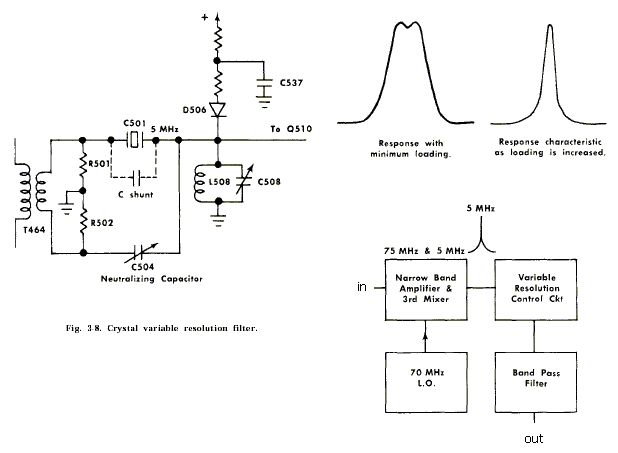
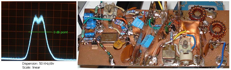
The problem is that when I measure the signal on the spectrum analyzer using maximum resolution (1khz on my analyzer), the top of the signal is as shown and the signal shows a bandwidth of 100KHz at -3db.

When I reduce the resolution, the signal shows a cleaner top and much less occupying bandwidth but still lot.

I thought that an unmodulated carrier occupies only a few HZ or 10s of Hz, am I wrong?
Also what about the effect of the resolution on the top of the signal, is that normal?
 
Last edited:

Your oscillator center frequency is jumping around, and the spectrum analyzer is simply showing the statistical points where it momentarily resides. If it is a tunable oscillator, try the following:

Run oscillator off battery
Run tune pin off resistor divider/battery
Put 220 uF in parallel with 1 uF ceramic cap on both VCC and Vtune ports
Use an inside/outside DC block to isolate the ground of the oscillator from the spectrum analyzers
Put a cardboard box over the vco so the air currents in the room do not modulate it.
Make sure VCO is not picking up any mechanical vibrations, like from a fan in the spectrum analyzer.

After that, the frequency spread will be smaller, but still non-zero due to thermal noise effects.

Rich
 
Last edited by a moderator:

Hello,

As Biff44 says, your frequency is jumping (unintended frequency modulation). Does the crystal read about 10 MHz? If this is the center frequency as shown on the spectral display, your transmitter is behaving really strange. This spectrum for an unmodulated crystal oscillator is too wide (as you noted yourself), even for a third or fifth overtone.

It will not surprise me when there is amplitude modulation present. Best is to first follow Biff44's advice, if this doesn't help, come back with us (circuit diagram may help).

If you have access to a wide band receiver (that enables wide FM demodulation on your transmitting frequency), you may listen to the signal. If it sounds clean switch from wide FM to narrow band FM. Did you check your analyzer with a stable signal to make sure your analyzer is OK?
 

Thank you all,
The oscillator is battery powered and there are decoupling caps near every active element. Maybe it is my measurement fault, I found something interesting for my analyzer which I present on the image

It seems that I have to turn the dispersion selector together with the coupled resolution in order to show at the same setting. I am not quite sure but I think that is what they mean by
"The resolution of the Type 491 Spectrum Analyzer is optimized for most settings of the DISPERSION selector when the RESOLUTION control is in the coupled position"
The outer double switch of the dispersion is connected (coupled) to the inner switch of the resolution. If you pull this inner switch, the two switches are no longer turn together at the same time. I guess it is this one..

If I use this process I cannot see any variation on the top of the signal. But I still get readings of about 100-200Hz bandwidth at -3db down from the top of the signal.
Is this nominal for an unmodulated carrier?
 

Hello,

A pure sine wave with a single frequency has zero bandwidth. However, due to noise there are always some frequency and amplitude variations. So what is called an unmodulated signal, is in reality a modulated signal (with noise), hence it has some bandwidth.

If you would apply a zero Hz wide carrier to a spectrum analyzer, you will always see a spectrum with wider bandwidth. This is caused by the bandwidth of the filter that provides the resolution bandwidth (and the quality of the internal oscillators). You mentioned that the best resolution is 1 kHz. This means that if you apply (for example) two unmodulated carriers 100 Hz apart, you will not see two separate peaks, but one peak that contains the power of both carriers.

You should see your analyzer as a large tuning range receiver with a certain IF bandwidth (RBW or resolution setting) where the Local Oscillator is swept across your frequency band of interest (start/stop frequency). The signal output of the IF filter is presented (in dB's mostly) as function of frequency. As it takes time for the signal to propagate through the IF filter, the sweep speed (MHz/s) is limited by the RBW setting. Small RBW results in large(r) sweep time.

In case of any doubt regarding settings, use a signal from wich you know it is clean (I don't know the purity of the analyzer's internal oscillators).
 
Last edited:
  • Like
Reactions: neazoi

    neazoi

    Points: 2
    Helpful Answer Positive Rating
Thank you very much! this is very helpfull!
 

You should be realistic. A tektronix 491 spectrum analyzer is a piece of junk. It does not even have a synthesized LO. You can not expect a signal to show up rock steady on one of those! Trade that in for at least a synthesized Spectrum analyzer, like an old 8566b or something.
 
  • Like
Reactions: neazoi

    neazoi

    Points: 2
    Helpful Answer Positive Rating
I agree biff44,
but look at the price of the 8566b. more than $3000 even today. Bought for $150 the old 491 is more than enough. And it can go double the high frequency (40GHz) than the 8566b. What you pay is what you get though. The 1 kHz analyzer resolution is probably setting my 3 dB point, which does not probably represent the signal bandwidth at that point, if I get it right....
 

If you want to look at close in phase noise 'on the cheap' then mix down to AF with a known clean source and look on a PC soundcard with some decent software that can produce a spectrum view.
 
  • Like
Reactions: neazoi

    neazoi

    Points: 2
    Helpful Answer Positive Rating
I agree biff44,
but look at the price of the 8566b. more than $3000 even today. Bought for $150 the old 491 is more than enough. And it can go double the high frequency (40GHz) than the 8566b. What you pay is what you get though. The 1 kHz analyzer resolution is probably setting my 3 dB point, which does not probably represent the signal bandwidth at that point, if I get it right....

Yeah, I know. Everything is sky high in price these days. But look at it this way, that 8566b cost as much as a nice house when it first came out. Now you can buy one for the price a couple kitchen appliances!

If you really want to go cheap, you can build a delay line frequency discriminator, and see the output on an oscilloscope. You just need a long low-loss coaxial cable to make one.
 
  • Like
Reactions: neazoi

    neazoi

    Points: 2
    Helpful Answer Positive Rating
If you want to look at close in phase noise 'on the cheap' then mix down to AF with a known clean source and look on a PC soundcard with some decent software that can produce a spectrum view.

Hm... I knew I could never perform phase noise measurements using the 491 when I bought it... It was just a matter of very good price for the ultra wide frequency range, the thing can go to 10MHz-40GHz. You can relatively measure harmonics, measure the carrier suppression in an ssb-sc signal but no close-to-carrier measurements, not at all :)
Wenzel associates has also proposed a relatively cheap way to measure phase noise. I am susceptible of the method you propose, because the mixer and all the parts in the chain must be of low phase noise too.

---------- Post added at 10:39 ---------- Previous post was at 10:23 ----------

If you really want to go cheap, you can build a delay line frequency discriminator, and see the output on an oscilloscope. You just need a long low-loss coaxial cable to make one.

There is something else I am thinking of. the analyzer uses the system below to define the resolution

If I use another more sharp filter I may be able to increase the resolution more.
I know resolution does not depend only on the IF filter but the IF filter bandwidth is a major factor.
Nevertheless I would expect greater resolution by the half lattice filter used, I thought you could go as low as 100Hz with such a filter and that is something I am wondering...
 

As you are building a small transmitter, you will probably have a receiver for it also. When, without modulation, the signal sounds clean, I think you don't have to worry about phase noise for your application. If you have a receiver capable of SSB/CW reception, listen to the beat frequency. If it sounds as a pure single frequency tone, your oscillator's short term stability is more then good for AM or FM.

You can use the analyzer to check for harmonics, subharmonics and side bands due to envelope instability (also called motor-boating).
 
  • Like
Reactions: neazoi

    neazoi

    Points: 2
    Helpful Answer Positive Rating
" I am susceptible of the method you propose, because the mixer and all the parts in the chain must be of low phase noise too"

You could use a reasonable DDS to generate an ultra low phase noise signal to beat with. Even if the DDS produces spurious terms you can rule these out by simply moving the DDS a few kHz and the spurs will move away.

Also, the sound card software can produce a resolution bandwidth below 1Hz so you would be able to see down past -120dBc/Hz very close to the carrier.

I've looked at DDS phase noise on an Agilent E5052A signal source analyser and they are capable of very low phase noise indeed :)

I don't think you need to worry about noise contribution from the signal path unless you want to make phase noise measurements that require something like a E5052A. eg -150dBc/Hz or better.
 
  • Like
Reactions: neazoi

    neazoi

    Points: 2
    Helpful Answer Positive Rating
You could use a reasonable DDS to generate an ultra low phase noise signal to beat with. Even if the DDS produces spurious terms you can rule these out by simply moving the DDS a few kHz and the spurs will move away.

Hi, GOHZU,
I really don't understand what you mean? you mean: if DDS output 1M, and have near end spurs, so set new DDS output at 1.005M, then spurs will go away. Is it true? Could you pls give more details about that?
 

No, he means as you look at the spectrum analyzer face, if you move the DDS frequency up 10 Hz, and another signal moves up 25 Hz simultaneously, you know it is a spur from the DDS, and not a spur from the component you are trying to test.
 
Status
Not open for further replies.

Part and Inventory Search

Welcome to EDABoard.com

Sponsor

Back
Top