Continue to Site

Welcome to EDAboard.com

Welcome to our site! EDAboard.com is an international Electronics Discussion Forum focused on EDA software, circuits, schematics, books, theory, papers, asic, pld, 8051, DSP, Network, RF, Analog Design, PCB, Service Manuals... and a whole lot more! To participate you need to register. Registration is free. Click here to register now.

Some questions about bicircular polarized antennas

Status
Not open for further replies.

antenna1895

Newbie level 5
Joined
Oct 15, 2022
Messages
9
Helped
0
Reputation
0
Reaction score
0
Trophy points
1
Activity points
137
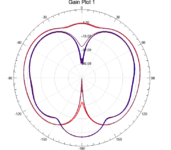
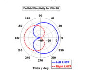
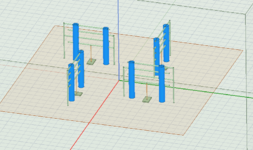
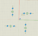
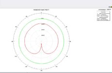
Dear master, today I simulate an antenna.My results are very different from the ideal results, when I want to increase the operating frequency (change the original structural parameters), the left-handed and right-handed circular polarization plots have changed dramatically, can you provide some ideas to solve this problem?(The left picture is my result ,the middle is the ideal result and the right is my model)
 

Attachments

  • 屏幕截图 2022-11-23 164830.png
    屏幕截图 2022-11-23 164830.png
    31 KB · Views: 104
  • 屏幕截图 2022-11-23 164845.png
    屏幕截图 2022-11-23 164845.png
    39.4 KB · Views: 97
  • 屏幕截图 2022-11-23 164907.png
    屏幕截图 2022-11-23 164907.png
    83.2 KB · Views: 121

The picture on the left is the edit sourses and the right one are the ports.(I use wave ports).Thanks for your reply.
 

Attachments

  • 屏幕截图 2022-11-25 084609.png
    屏幕截图 2022-11-25 084609.png
    28.3 KB · Views: 112
  • 屏幕截图 2022-11-25 084628.png
    屏幕截图 2022-11-25 084628.png
    25.7 KB · Views: 92

Although it's difficult to tell which objects are your wave ports, I would guess that likely either the individual elements you have there are enforcing too linear a polarization, or your simulation is not adequately meshed.

I would lean towards the latter -- could you post your convergance settings and meshing/convergance results?
 
Thanks for your reply, I set ten as the maximum number of iterations.But in fact,there are only four. Maybe that's the problem?And could you give me some advice?
 

Attachments

  • 屏幕截图 2022-11-26 100522.png
    屏幕截图 2022-11-26 100522.png
    26.1 KB · Views: 99
  • 屏幕截图 2022-11-26 100747.png
    屏幕截图 2022-11-26 100747.png
    22.3 KB · Views: 102
  • 屏幕截图 2022-11-26 100758.png
    屏幕截图 2022-11-26 100758.png
    22.3 KB · Views: 93

That doesn't look too bad, but it's hard to tell. Under "Options" set minimum converged passes to 5, and see if anything changes. It will take a while to run, but if the results change then there is a problem with the convergence. If you get the same results, then it might be something else in your setup.
 
It is difficult to interpret a plot with no legend and no labels.
I will improve , thanks

That doesn't look too bad, but it's hard to tell. Under "Options" set minimum converged passes to 5, and see if anything changes. It will take a while to run, but if the results change then there is a problem with the convergence. If you get the same results, then it might be something else in your setup.
I will try ,thank you very much

Here is my project.
--- Updated ---

That doesn't look too bad, but it's hard to tell. Under "Options" set minimum converged passes to 5, and see if anything changes. It will take a while to run, but if the results change then there is a problem with the convergence. If you get the same results, then it might be something else in your setup
I am sorry to trouble you again, I set minimum converged passes to 5,but everything is the same. I try to improve the frequency but I fail to meet the requests for dual circular polarization.(In the paper which I try to simulate,the frequency is on the UHF.)
 

Attachments

  • Project1.zip
    113.5 KB · Views: 95
Last edited:

I am curious how you can really build this antenna, do you have prototype photo to show, or any resource paper?
Actually I know the answer for you.
Best,
Tony Liu
 
o
I am curious how you can really build this antenna, do you have prototype photo to show, or any resource paper?
Actually I know the answer for you.
of course, thank you very much. I have successfully reproduced this model, and I try to improve the frequency for miniaturization. Now, I try to change the reflectively for suppress the antenna posterior lobe.
--- Updated ---

o

of course, thank you very much. I have successfully reproduced this model, and I try to improve the frequency for miniaturization. Now, I try to change the reflectively for suppress the antenna posterior lobe.
But can IEEE papers be uploaded like this?
 

Attachments

  • Compact_Low-profile_Low-mass_UHF_Folded_Shorted_Dipole_Antenna_Array_with_Dual_Circular_Polari...pdf
    1 MB · Views: 104

I used your HFSS file, and got the result as the attachment, is that similiar to the ideal?
Hope that can help you.
 

Attachments

  • 捕获.JPG
    捕获.JPG
    70.1 KB · Views: 91
Status
Not open for further replies.

Part and Inventory Search

Welcome to EDABoard.com

Sponsor

Back
Top