rockman139
Newbie level 2

- Joined
- Mar 5, 2013
- Messages
- 2
- Helped
- 0
- Reputation
- 0
- Reaction score
- 0
- Trophy points
- 1,281
- Activity points
- 1,302
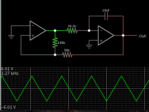
I have tested my triangular wave generator on the bread board according to the schematic below, but I have some problems and I don't know what is happening.

The amplitude of the triangular wave should be calculated like this:
2×(R1/R2)×Vcc=2×50k/100k×12=12V
The frequency of the triangular wave should be calculated as below:
R2/(4×R1×R3×C)=100K/(4×50k×39.2k×10n)=1275Hz
However, I can't get these results.

I switched the observed amplitude to 1 and the time to be 0.5ms as the picture showed.

Vertically, the triangular wave just occupied a little more than one slot, hence the amplitude is 1.4V
horizontally, it occupied 2 slots, hence the time is 2×0.5=1ms, the frequency is 1000Hz.
Is it any problem with the selection of R1, R2 and R3? What values of the resistance should I choose?
And the results are so different to the theoretical calculations. Can anybody help me? Please!
The amplitude of the triangular wave should be calculated like this:
2×(R1/R2)×Vcc=2×50k/100k×12=12V
The frequency of the triangular wave should be calculated as below:
R2/(4×R1×R3×C)=100K/(4×50k×39.2k×10n)=1275Hz
However, I can't get these results.
I switched the observed amplitude to 1 and the time to be 0.5ms as the picture showed.
Vertically, the triangular wave just occupied a little more than one slot, hence the amplitude is 1.4V
horizontally, it occupied 2 slots, hence the time is 2×0.5=1ms, the frequency is 1000Hz.
Is it any problem with the selection of R1, R2 and R3? What values of the resistance should I choose?
And the results are so different to the theoretical calculations. Can anybody help me? Please!