Continue to Site

Welcome to EDAboard.com

Welcome to our site! EDAboard.com is an international Electronics Discussion Forum focused on EDA software, circuits, schematics, books, theory, papers, asic, pld, 8051, DSP, Network, RF, Analog Design, PCB, Service Manuals... and a whole lot more! To participate you need to register. Registration is free. Click here to register now.

Solder bridge or 0 Ohm resistor

Status
Not open for further replies.

cane21

Junior Member level 1
Joined
Aug 19, 2018
Messages
15
Helped
0
Reputation
0
Reaction score
0
Trophy points
1
Activity points
105
Hi all,

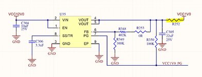
If I’d like to isolate the output of my voltage regulator from the power plane, would it be better to use a solder bridge/blob or a 0 ohm resistor?

If the regulator voltage output is max 10A @ 1.2V what is the maximum current that an 0805 sized solder blob can carry and how would I select a 0 ohm Resistor for this purpose?
 

Hi,

if you want to isolate then neither a solder bridge nor a 0 Ohms resistor is needed.

Klaus
 

Hi,

if you want to isolate then neither a solder bridge nor a 0 Ohms resistor is needed.

Klaus
Sorry, to be more specific I meant I want to isolate it until I’m sure the voltage is correct before connecting it to the plane.
 

Hi,
I´m still not sure....

If you want to "disconnect" the voltage regulator, then you should do this on the positive side, not at GND. I strongly recommend this.
Besides unknown behaviour when GND is disconnected...even when connected you add GND impedance resulting in accuracy errors, maybe stability problems.

Klaus
By positive side do you mean the input side of the regulator? If I disconnect the input side then I won’t be able to measure my output voltage to ensure it’s correct

Let me try again :

I have a 12V to 1V/1.2V/0.85V voltage regulator to power an FPGA. I don’t want the FPGA powered up as soon as I switch on. I first want the regulator to come on so that I can ensure the output voltages are correct and then only have those voltages feeding the relevant planes.
On some boards I have they’ve just used solder blob/bridge on the Voltage output of the regulator for this purpose.


I hope this clarifies it?
 

Solder bridge or 0 Ohm resistor


What is the electrical difference?

Additionally, if you want to isolate the ground and measure the output voltage, the readings may be unreliable (unreferenced). The readings may change if you connect to a new ground after measuring the output voltage.


It is good to spell out in detail the objective and the preferred way (your way) of executing the scheme. You also need to have some idea of the expected result with which you can actually compare the observed result.

Your response has come in the meantime.

But this is still not clear. You say:

I don’t want the FPGA powered up as soon as I switch on. I first want the regulator to come on so that I can ensure the output voltages are correct and then only have those voltages feeding the relevant planes.​

But how this is done with a solder bridge or a 0 Ohm resistor?
 

Hi,

By positive side do you mean the input side of the regulator?
Input or output. Just not GND.

******

--> by disconnecting GND you won´t be able to measure the output voltage, too.

The only way I see is to disconnect the output.
But are you sure you really want this? .. Manually ... with this series impedance....

Klaus
 

Most of the discussion seems to be about misunderstandings. The OP states to disconnect the regulator output from power plane, not ground plane.

Quality manufacturers have specifications for SMD jumpers. Vishay is e.g. specifying 2.5 A rating for 0805 standard series thick film jumper. High current jumpers with metal bridge are available but more expensive, e.g. https://www.seielect.com/catalog/sei-hcj.pdf

Solder bridge is only feasible with hand soldering, but can work.
 

    cane21

    Points: 2
    Helpful Answer Positive Rating
Most of the discussion seems to be about misunderstandings. The OP states to disconnect the regulator output from power plane, not ground plane.

Quality manufacturers have specifications for SMD jumpers. Vishay is e.g. specifying 2.5 A rating for 0805 standard series thick film jumper. High current jumpers with metal bridge are available but more expensive, e.g. https://www.seielect.com/catalog/sei-hcj.pdf

Solder bridge is only feasible with hand soldering, but can work.
Yes, that is exactly what I'm asking. What would be the maximum that an 0805 size solder bridge can withstand? Are there any rules of thumb to estimate?

I have made a quick schematic to illustrate my question with R252 being the solder bridge or jumper resistor.
 

Attachments

  • Schematic.JPG
    Schematic.JPG
    195.7 KB · Views: 160

Here are small solder jumpers that I have used in a project, 1 mm width, 0.2 mm pad clearance. I would probably increase the width for 10A.

1621604697346.png
 

What about a header post pair and clip? Like you see on PC motherboard and HDDs for user jumper options? Good for clipping on a probe, and later you can replace with a bit of wire.
 

if this is linear regulator, you can just use a bench supply as your input and slowly raise the input voltage until you see the regulator start to regulate. That way, you can prevent an overvoltage at the regulator output. Note that this won't work for switching regulators.
 

Status
Not open for further replies.

Part and Inventory Search

Welcome to EDABoard.com

Sponsor

Back
Top